Another "how do you model this" post...
 1-20  21-25

Next
 From:  paulrus
4947.1 
I'm sorry to post this, because I think this is a really simple object to model, but the embossing at the top is giving me fits. I know exactly how I'd model it in Softimage, but I want to try it in MOI.

As you can see in the attached image, the top of this electric motor has an embossed pattern and then also around the entire circumference of the cylinder, the edges have a filet.


All I can think to do is cut out the shape and then blend each edge individually.

Any thoughts?

Thanks,

Paul
Attachments:

  Reply Reply More Options
Post Options
Reply as PM Reply as PM
Print Print
Mark as unread Mark as unread
Relationship Relationship
IP Logged

Previous
Next
 From:  Michael Gibson
4947.2 In reply to 4947.1 
Hi Paul, probably something like:

Create a cylinder:


Go to the top view and draw in your wedge shape:


Extrude it:


Select the extruded plug and do Transform > Array > Circular to replicate it:


Select the cylinder and do Construct > Boolean > Difference and pick the plugs as the cutting objects:


Now you can just select the whole object:


And run Fillet to round off the corners:


For filleting you can select an entire object as the input to fillet which fillets all sharp edges of that object. If you need to target specific edges you can pick just some edges - in a case like this select just 1 edge to go into edge sub-object mode and then go to a side view and do a window select to grab a whole bunch more by capturing them within one drag window selection.

Hope this helps!

- Michael

  Reply Reply More Options
Post Options
Reply as PM Reply as PM
Print Print
Mark as unread Mark as unread
Relationship Relationship
IP Logged

Previous
Next
 From:  paulrus
4947.3 In reply to 4947.2 
Man it's hard for me to think like that!

I never would have thought of building an array and using that to boolean.

I'll have to give that a try right now.

Thanks!!

Paul
  Reply Reply More Options
Post Options
Reply as PM Reply as PM
Print Print
Mark as unread Mark as unread
Relationship Relationship
IP Logged

Previous
Next
 From:  Stever_uk (STEVER)
4947.4 In reply to 4947.3 
Hi Paul,

Yes I was saying the same thing last year, but you will pick it up just takes a little time.
Now I hardly touch polygonal/subd modelling

If I can anyone can !!:)
  Reply Reply More Options
Post Options
Reply as PM Reply as PM
Print Print
Mark as unread Mark as unread
Relationship Relationship
IP Logged

Previous
Next
 From:  Mike K4ICY (MAJIKMIKE)
4947.5 
Hi Paul!

I thought I'd add my perspective on how to create your motor top.
This one is geared towards a more intermediate skill level, but there may be something you like in it.

I borrow some of the elements of my last tutorial. Here I'll create shapes, and blend associated edges.

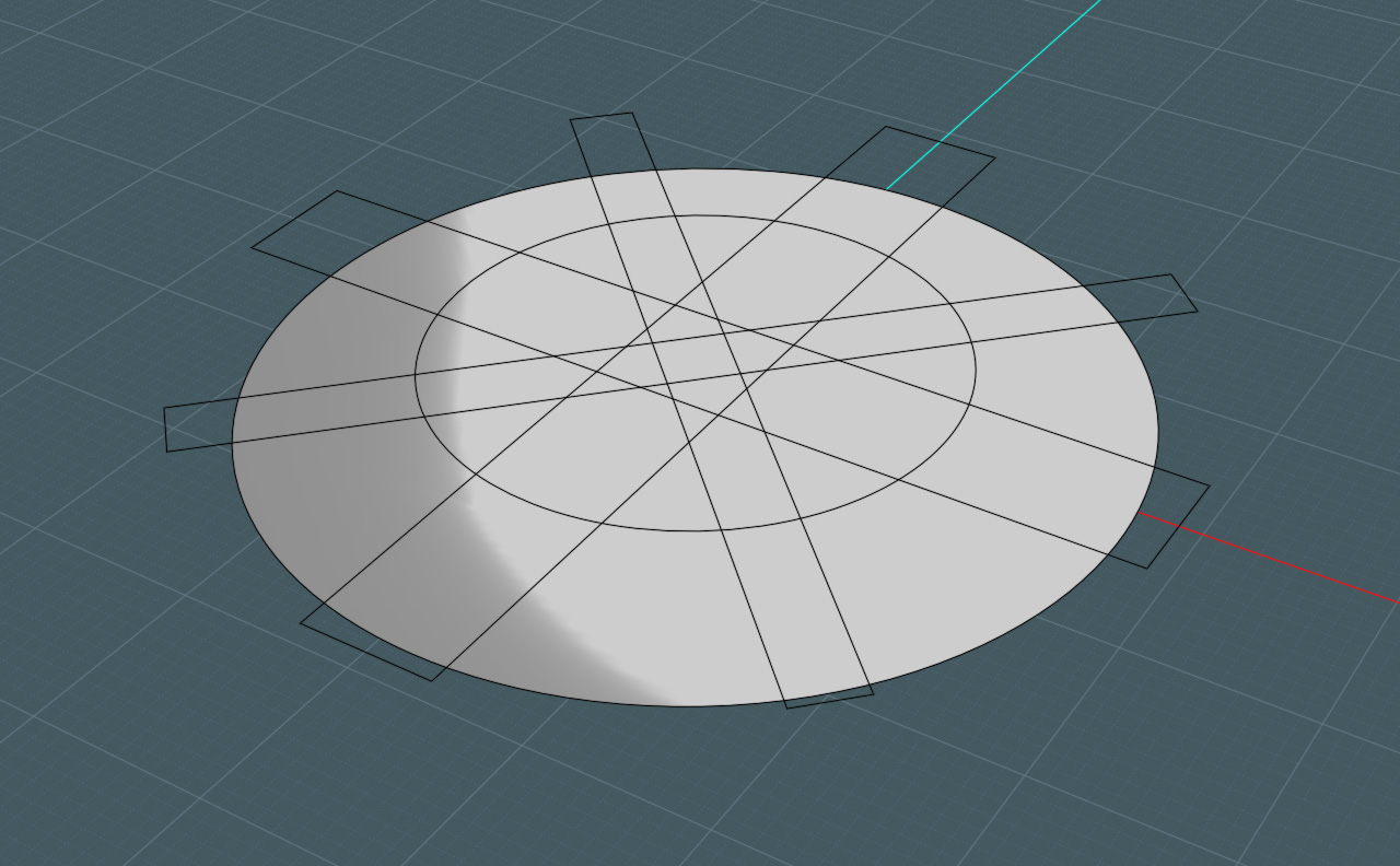
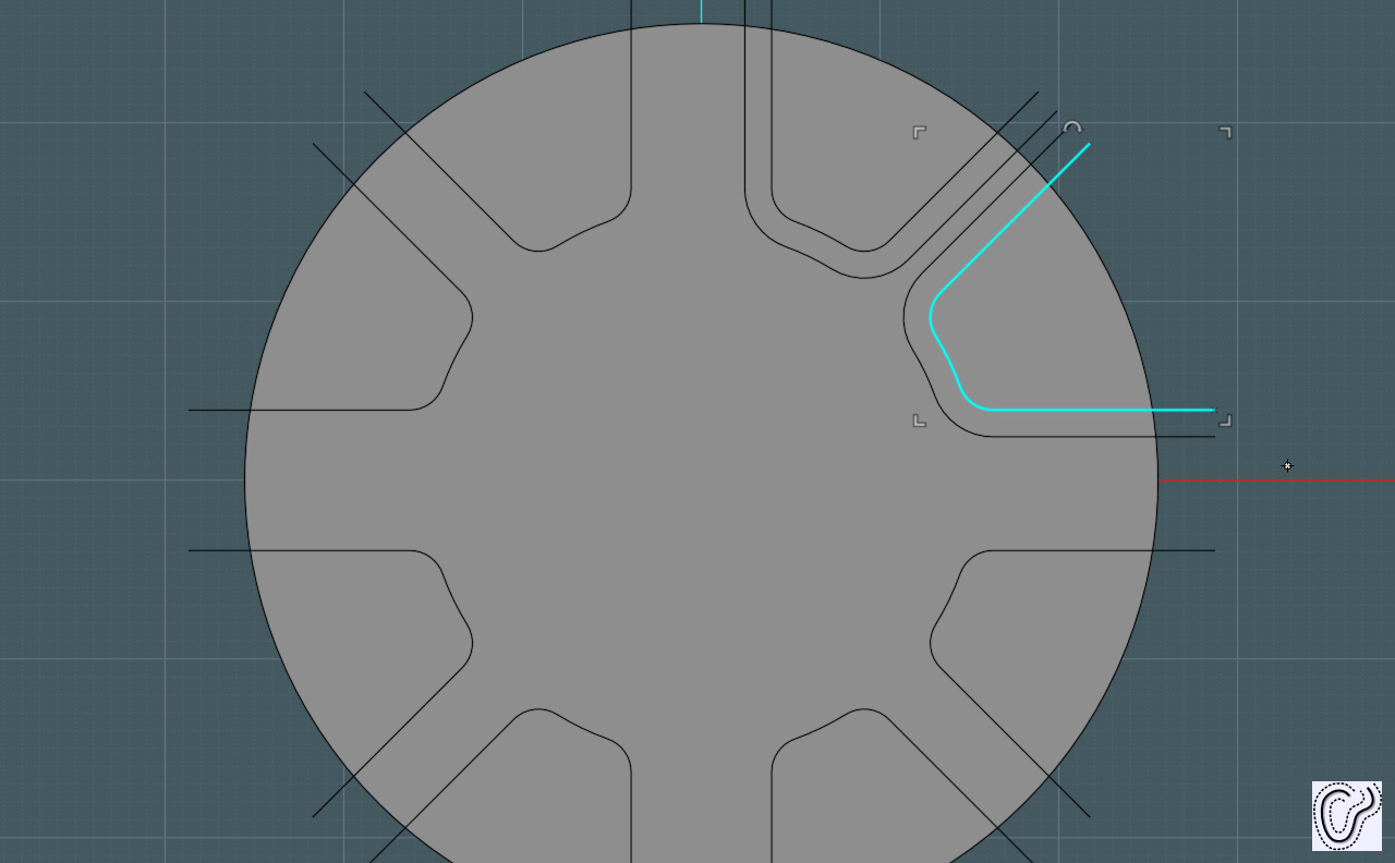
Step 1 - Draw your basic shapes.
This includes the large circle, an inner circle to define the inside part of those divots, and a rotated series of rectangles to define the sides.


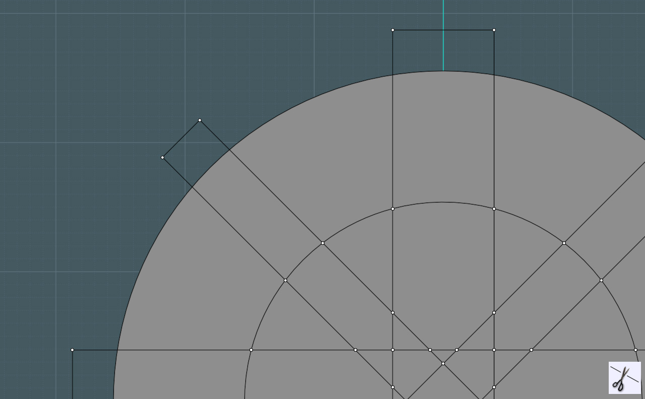
Step 2 - I trim all these rectangles and the inner circle shape to get my smaller edges.
I delete whatever I do not need.


Step 3 - I then Join the remaining curves to make my divot shapes.
Then I Fillet the corners to round them off.


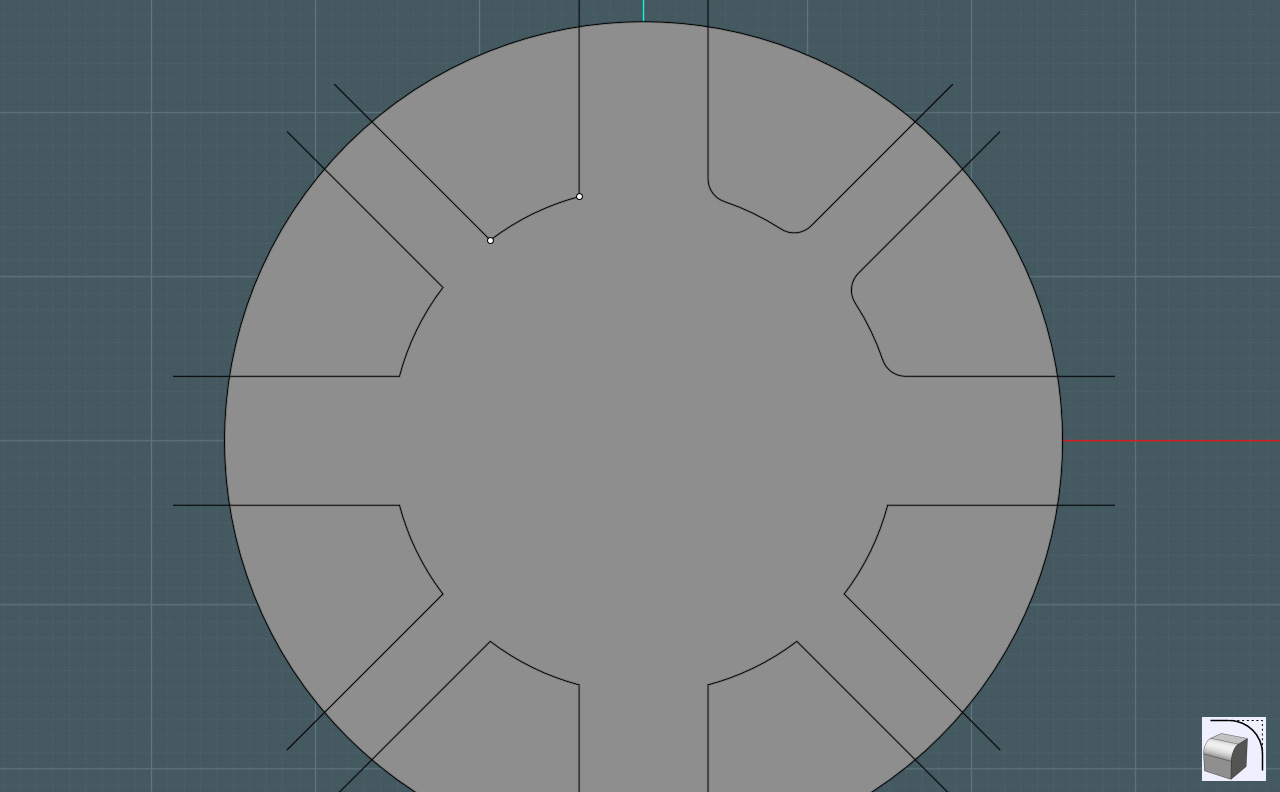
Step 4 - I now use the Offset command on the curves to make smaller or larger versions of the divot shapes.
Maintain the rounded edges.


Step 5 - Once the divot shapes and their associated counterparts are created, you can perform a Boolean Difference to make different sections of the base circle below.


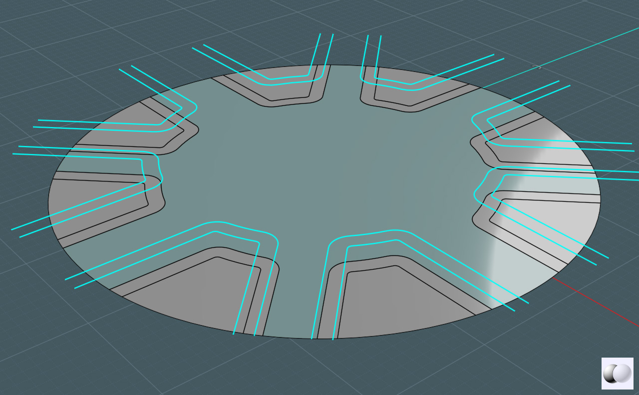
Step 6 - Simply delete what you don't need and move the inner divot shapes down a little.


Step 7 - The curve edges defining the divot shapes, in both the main circle and the lower shapes may be cut into several segments.
Go ahead and collect them, then run the "Merge" command in the text input field and make them singular edge curves.
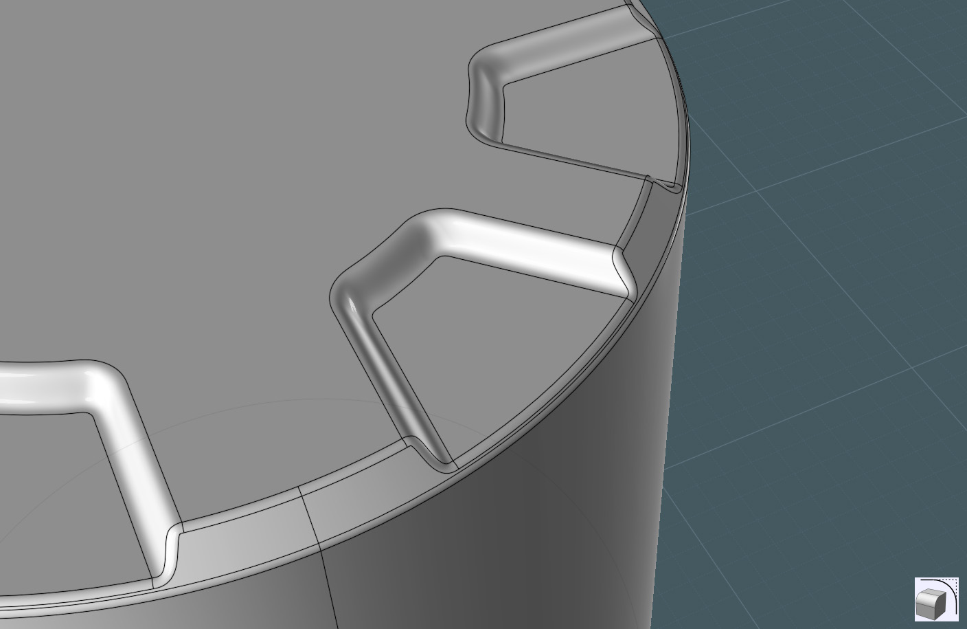
Next, perform the Blend command on the surface edges. Join those edges to the main circular shape.


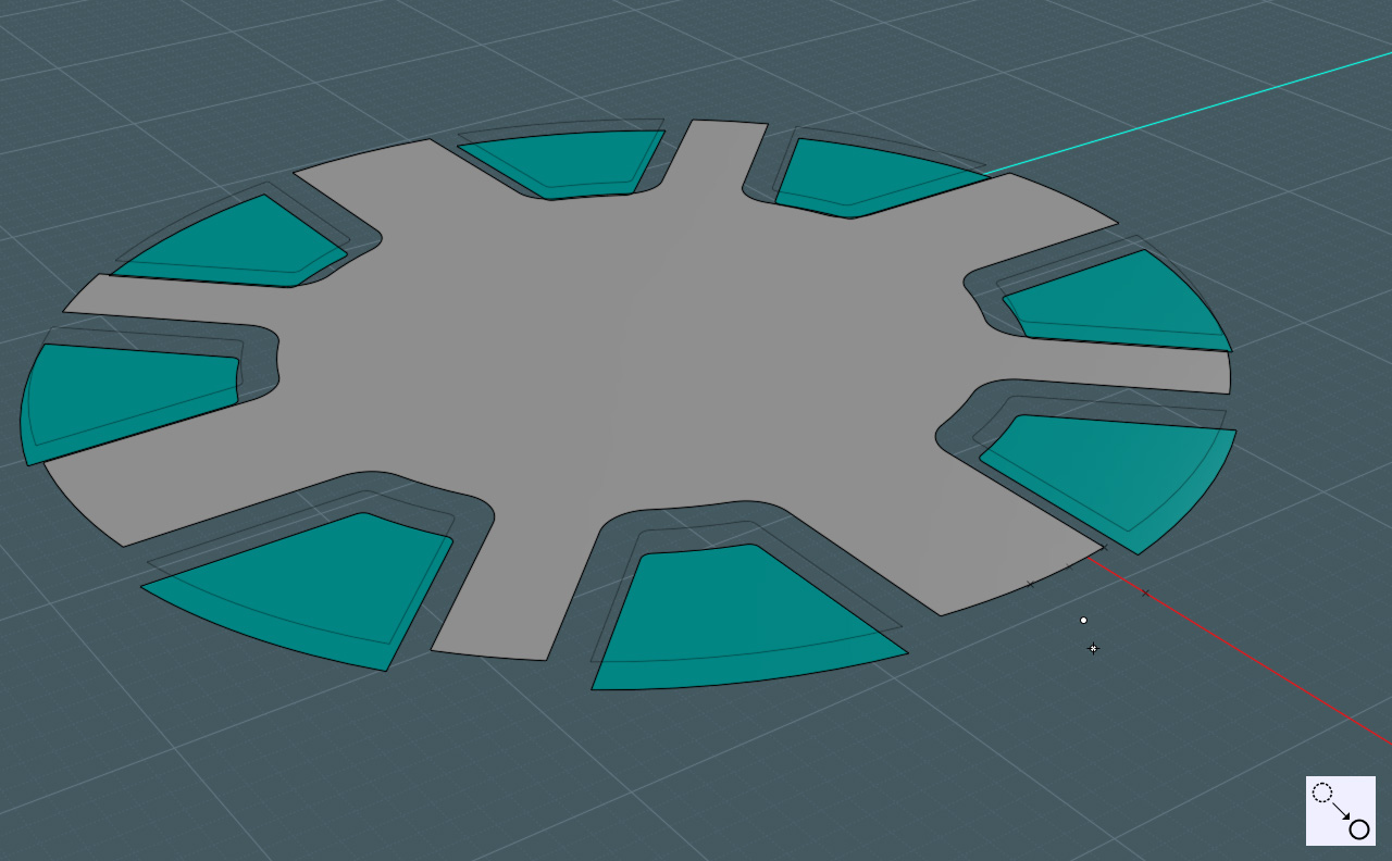
Step 8 - It's nice to have a solid to work with. Select the edge curves of this new shape and use the Extrude command to make something more solid.
Don't worry about the strange side surfaces.


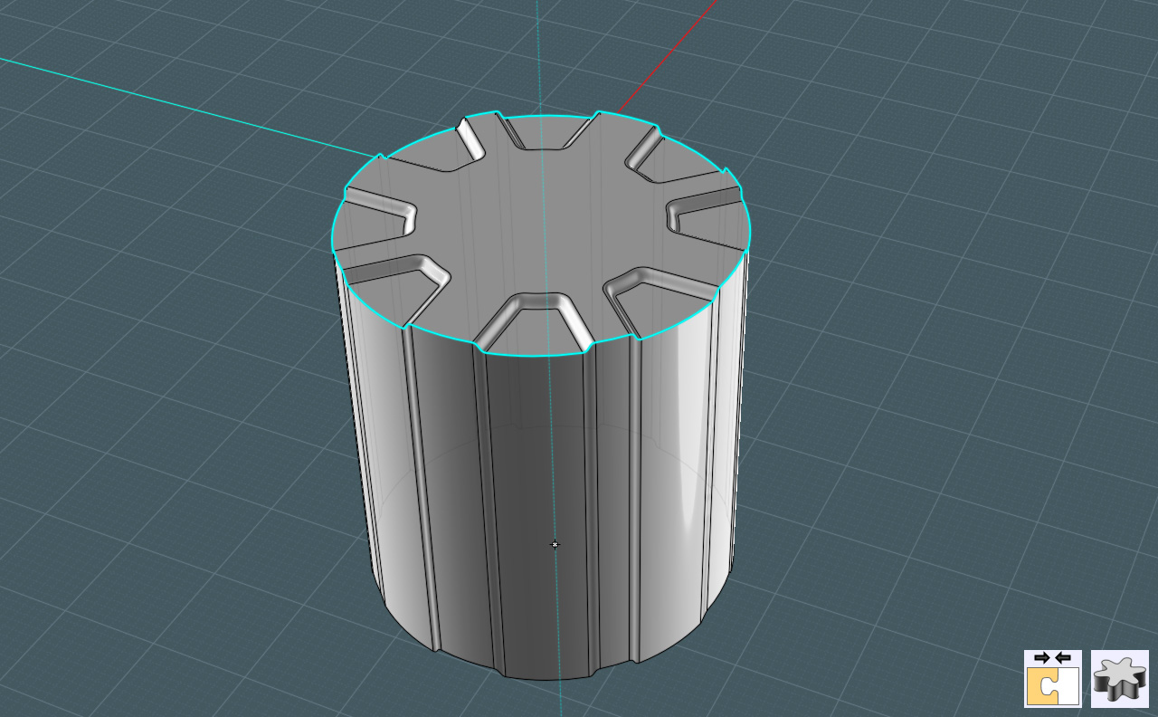
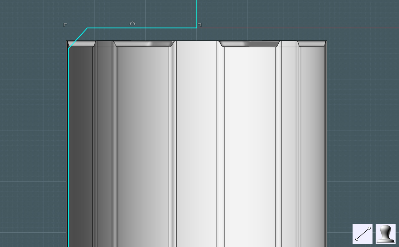
Step 9 - I want to get a nice mitered shape to the motor top and I want to clean up the strange edges.
I make a profile with a nice cut miter and I Revolve the profile to make a solid.


Step 10 - I use Boolean Intersect to get the best of both solids. Now I have something more close to what I want.


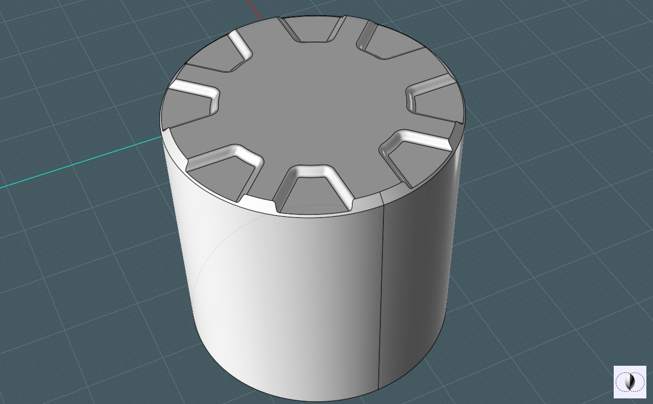
Step 11 - Lets clean it up a little and Fillet the edges to make a nice machined look. Keep in mind earlier on to allow enough space in your construction to have room for the Fillets.


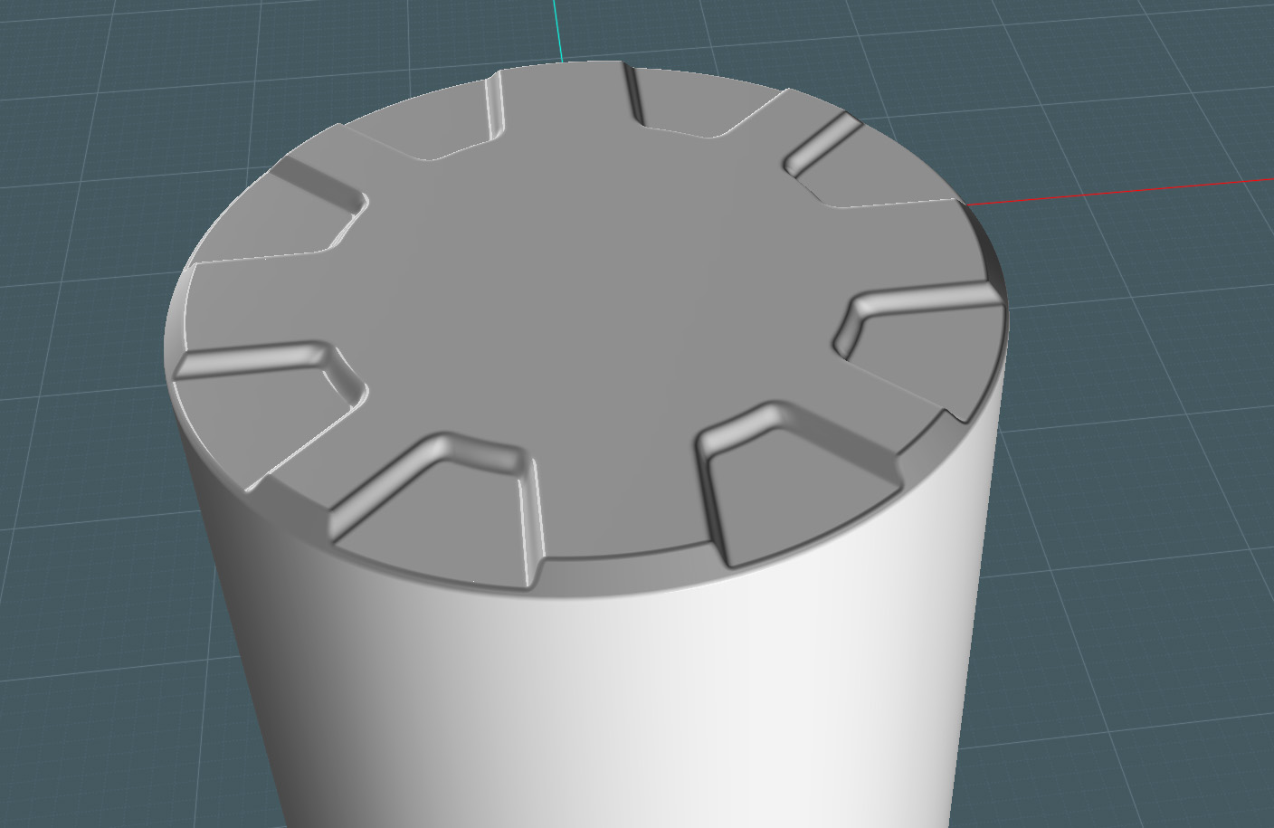
Here you go! Simply another way the MoI is able to accomplish the task at hand.

  Reply Reply More Options
Post Options
Reply as PM Reply as PM
Print Print
Mark as unread Mark as unread
Relationship Relationship
IP Logged

Previous
Next
 From:  Stever_uk (STEVER)
4947.6 In reply to 4947.5 
yes Mike a little more complexed but wow what a result !!

I going to give this a go :)

Great Stuff
  Reply Reply More Options
Post Options
Reply as PM Reply as PM
Print Print
Mark as unread Mark as unread
Relationship Relationship
IP Logged

Previous
Next
 From:  Rich_Art
4947.7 In reply to 4947.5 
Very very nice Mike.

Peace,
Rich_Art. ;-)

| C4DLounge.eu | Our Dutch/Belgium C4D forum. |
  Reply Reply More Options
Post Options
Reply as PM Reply as PM
Print Print
Mark as unread Mark as unread
Relationship Relationship
IP Logged

Previous
Next
 From:  paulrus
4947.8 In reply to 4947.5 
Really cool technique!

It's so hard for me to wrap my polygon-thinking brain around these things sometimes.

Paul
  Reply Reply More Options
Post Options
Reply as PM Reply as PM
Print Print
Mark as unread Mark as unread
Relationship Relationship
IP Logged

Previous
Next
 From:  Frenchy Pilou (PILOU)
4947.9 
Another cool tut!
---
Pilou
Is beautiful that please without concept!
My Gallery
  Reply Reply More Options
Post Options
Reply as PM Reply as PM
Print Print
Mark as unread Mark as unread
Relationship Relationship
IP Logged

Previous
Next
 From:  Mike K4ICY (MAJIKMIKE)
4947.10 In reply to 4947.8 
As the Great Kahuna BurrMan said: Just think of MoI in terms of fluid curves and surfaces and just ride the waves, and all is Zen mannnn....
(or was that the Great Moai?) ;-)
  Reply Reply More Options
Post Options
Reply as PM Reply as PM
Print Print
Mark as unread Mark as unread
Relationship Relationship
IP Logged

Previous
Next
 From:  BurrMan
4947.11 In reply to 4947.10 
That was Kimo that said that!!! :o (Though it sounds a little Spiccolli)

There is normally a big divide between CAD modelers and poly modelers. Majik is a great "Blend" of the 2!!!
  Reply Reply More Options
Post Options
Reply as PM Reply as PM
Print Print
Mark as unread Mark as unread
Relationship Relationship
IP Logged

Previous
Next
 From:  Marc (TELLIER)
4947.12 In reply to 4947.11 
Great tutorial mike!

I don't think often of using intersection.

Marc
  Reply Reply More Options
Post Options
Reply as PM Reply as PM
Print Print
Mark as unread Mark as unread
Relationship Relationship
IP Logged

Previous
Next
 From:  DannyT (DANTAS)
4947.13 In reply to 4947.5 
Nice tute Mike.

Tip: In Step 2. instead of trimming, select all the curves and hit Boolean>Union.

Cheers
~Danny~
  Reply Reply More Options
Post Options
Reply as PM Reply as PM
Print Print
Mark as unread Mark as unread
Relationship Relationship
IP Logged

Previous
Next
 From:  Mike K4ICY (MAJIKMIKE)
4947.14 In reply to 4947.13 
Ah yes! Thanks Danny, I keep meaning to try that.

I use Trim generally for smaller isolated single curve-to-curve editing and it's a force of habit now.
  Reply Reply More Options
Post Options
Reply as PM Reply as PM
Print Print
Mark as unread Mark as unread
Relationship Relationship
IP Logged

Previous
Next
 From:  BurrMan
4947.15 In reply to 4947.14 
Here's one where I mix 2 radius fillets into that lower area.

  Reply Reply More Options
Post Options
Reply as PM Reply as PM
Print Print
Mark as unread Mark as unread
Relationship Relationship
IP Logged

Previous
Next
 From:  Mike K4ICY (MAJIKMIKE)
4947.16 In reply to 4947.15 
You are the man Burr!
You pulled that off in under 4 minutes!
  Reply Reply More Options
Post Options
Reply as PM Reply as PM
Print Print
Mark as unread Mark as unread
Relationship Relationship
IP Logged

Previous
Next
 From:  BurrMan
4947.17 In reply to 4947.16 
Hahahaaaa. Well, if speed was the goal, then it would be hard to beat simple extrudes and fillets, but the result is not near the beautiousness of that blended/mitered piece you presented.. You KNOW I love the blend!
  Reply Reply More Options
Post Options
Reply as PM Reply as PM
Print Print
Mark as unread Mark as unread
Relationship Relationship
IP Logged

Previous
Next
 From:  Rich_Art
4947.18 In reply to 4947.15 
Cool solutions....

Thanks for showing.

Peace,
Rich_Art. ;-)

| C4DLounge.eu | Our Dutch/Belgium C4D forum. |
  Reply Reply More Options
Post Options
Reply as PM Reply as PM
Print Print
Mark as unread Mark as unread
Relationship Relationship
IP Logged

Previous
Next
 From:  Mauro (M-DYNAMICS)
4947.19 In reply to 4947.11 
>Burr>(Though it sounds a little Spiccolli)

what you mean"Spiccolli"?


>Burr
Majik is a great "Blend" of the 2!!!

LOL..that's great !!!
-----------------------

Mike: sophisticated like ever!
  Reply Reply More Options
Post Options
Reply as PM Reply as PM
Print Print
Mark as unread Mark as unread
Relationship Relationship
IP Logged

Previous
Next
 From:  paulrus
4947.20 In reply to 4947.19 
In case anyone was wondering, here's how my version turned out:


Everything but the cable, the screws and the plugs were done in MOI. It was rendered in Softimage with Arnold.

Thanks!

Paul
Attachments:

  Reply Reply More Options
Post Options
Reply as PM Reply as PM
Print Print
Mark as unread Mark as unread
Relationship Relationship
IP Logged
 

Reply to All Reply to All


Show messages:  1-20  21-25