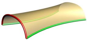
> The rail revolve is probably the appropriate tool at this point for this type
> of shape, then tweak the control points to get the desired contour.
Yeah, at the moment this seems like the best way for this particular shape. But I definitely want to make this work better through a curve construction technique as well instead of relying on surface point tweaking. Network surface is probably the one, but I'm also pretty interested in fixing up Sweep so that it would work better for this.
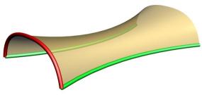
Actually, Network surface will only really be better for doing the full object but for doing the half object network surface will have some similar problems as sweep in that there will still be some cross-sectional rotation especially in the last sections where things come together to a point.
Running through this has given me an idea to try for sweep, which is to see if all the profiles are on parallel planes, and if they are then create each in-between new cross-section on that same plane. This would eliminate rotation of the profiles and should result in something that can be cleanly mirrored.
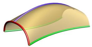
It is nice if it is possible to model a clean half of a model, it is sort of less hassle to tweak the shaping by editing a half a curve instead of worrying about editing a symmetrical curve and keeping it symmetrical.
> Also, is there a way to flatten curves in one op?
One way is to turn on points for the curve, select all the points and use Transform/Align - then pick your alignment location in the front or side view with horizontal alignment.
At some point I would like to add a one step project function that didn't make you turn on points, but I haven't quite figured out where to place that in the UI, like whether it should go in some sub-function of align or have to be its own separate tool.
- Michael
|