Part Two: Hand-Held Shower Head Body
Here I will create a decorative body for the shower head.
BTW, this shower head is a hand-held model.
I've put a few days of thought into this. It needed to match the decor of my WIP bathroom scene.
I had some fancy designs in mind, but this is a fixture that is used every-day, and since it is hand-held, it needs to be sort of basic in overall shape.
Though, it can have a little pizazz put into it.
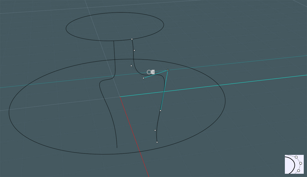
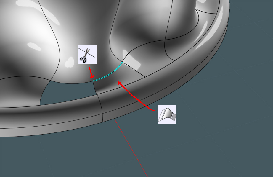
We need to draw profiles to make the main body shape with the Network command.
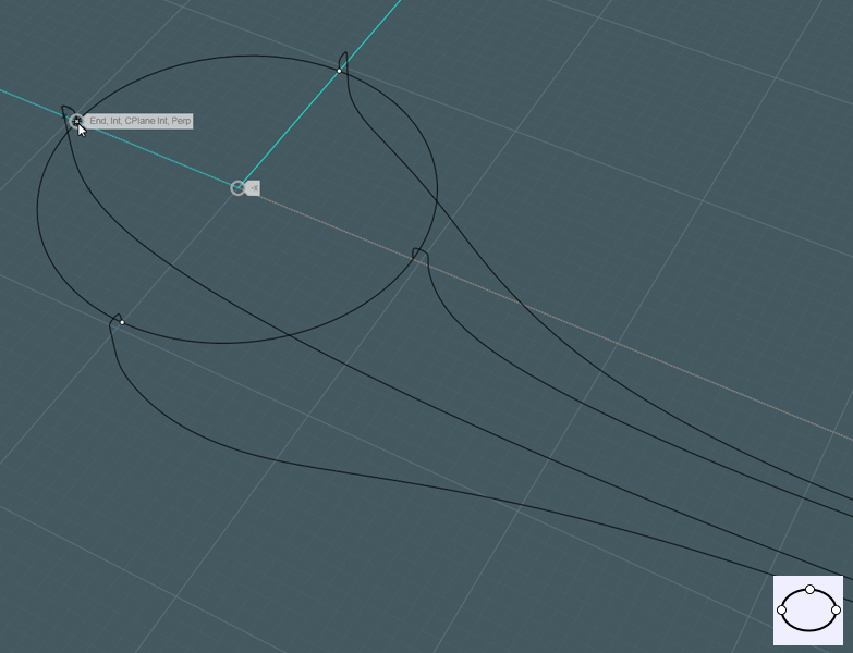
1) Freeform curves to make up a top and bottom profile line to run down the center (looking from the face)
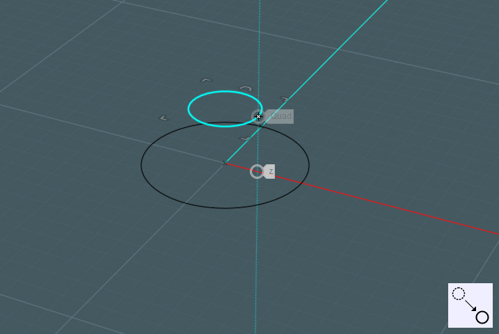
Used the shower nozzle face and it's circle as a reference.
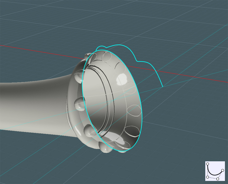
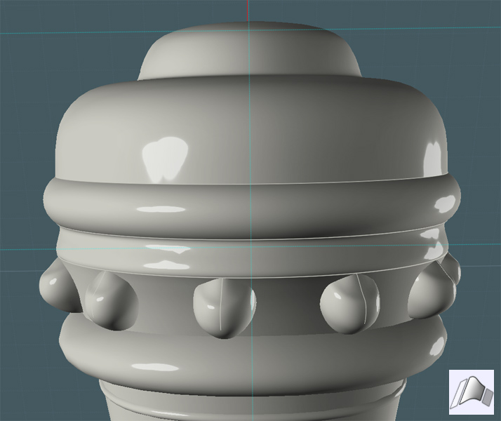
Notice how I made a lip shape to hold the nozzle head...
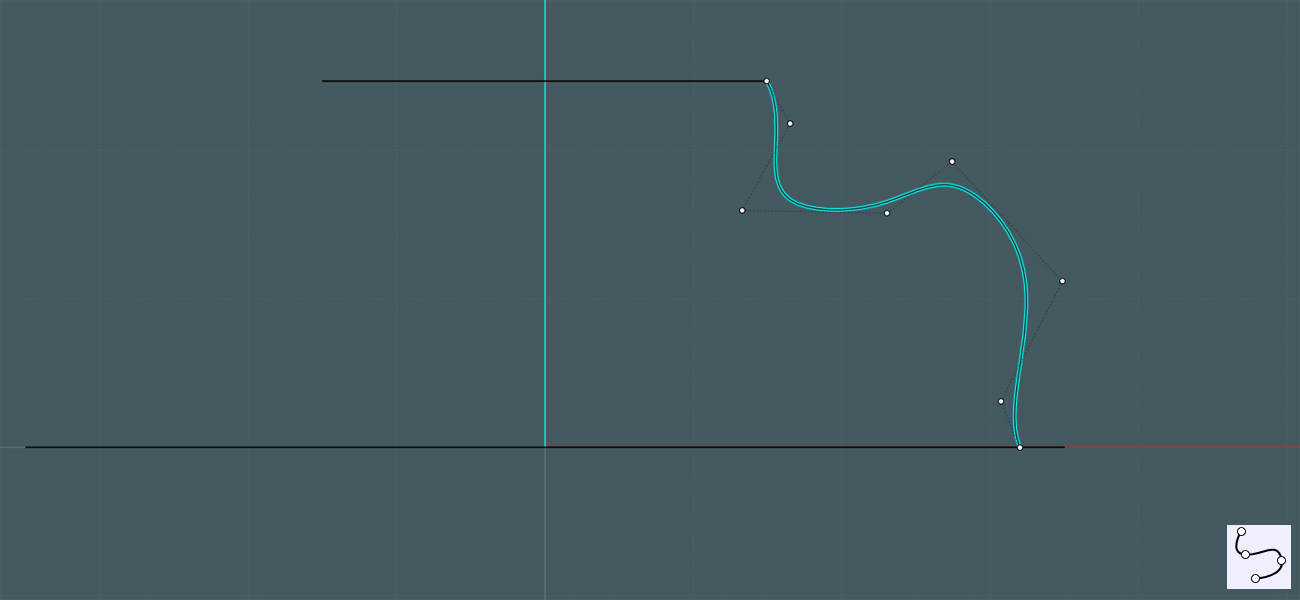
Now we need a symmetrical profile curve to represent the sides of the shower handle body.
2) Started in Right View and made the lip.
3) Then I continued drawing points for the curve in the Front/Back Views to carry the profile along the body.
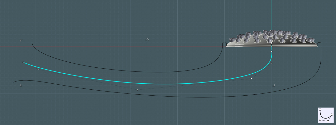
4) I went into the Top View and shown the points of the curves, manipulating them to give it a nice curved shape from the top.
5) Mirror Command - to make the symmetrical copy of the side profile.
Note: By manipulating the points of the original shape, adjustments can be made to the mirror copy simultaneously by it's history state.
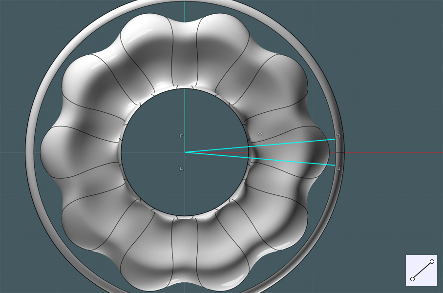
You can see the arrangement in 3D View...
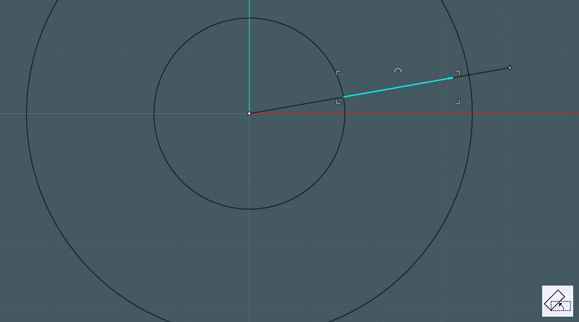
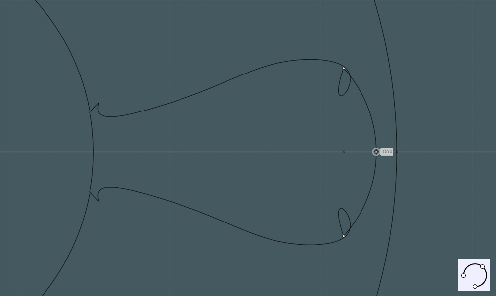
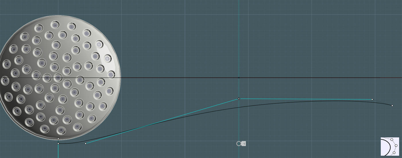
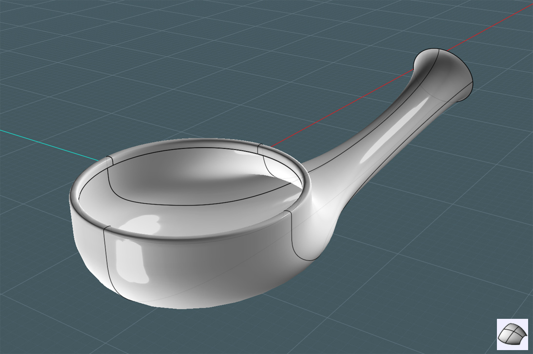
To make a simple "Axial" Network surface, we now need at least two profile rings at each end of the profile rails created.
This one is simple:
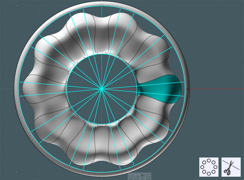
6) Use the Ellipse by Diameter tool, select two opposite end points, then and adjacent point/ (As shown)
Because I used the original circle for the shower nozzle face as reference, the fourth side of the ellipse touched the remaining profile rail end.
However, you don't have to be dead-on for Network to work.
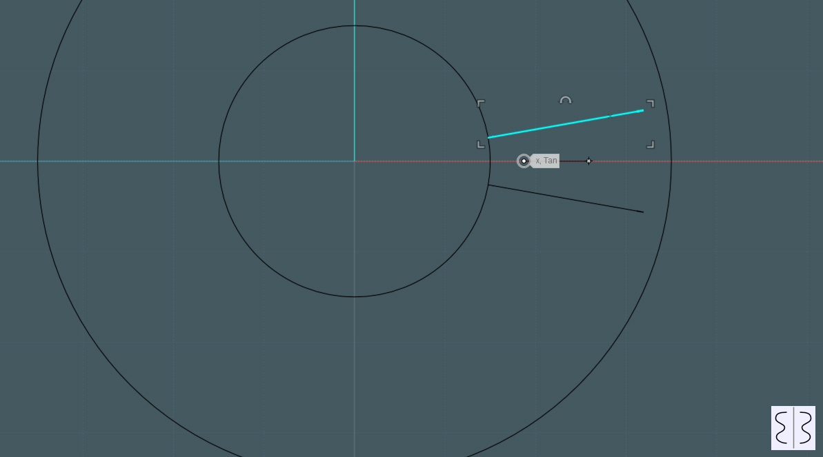
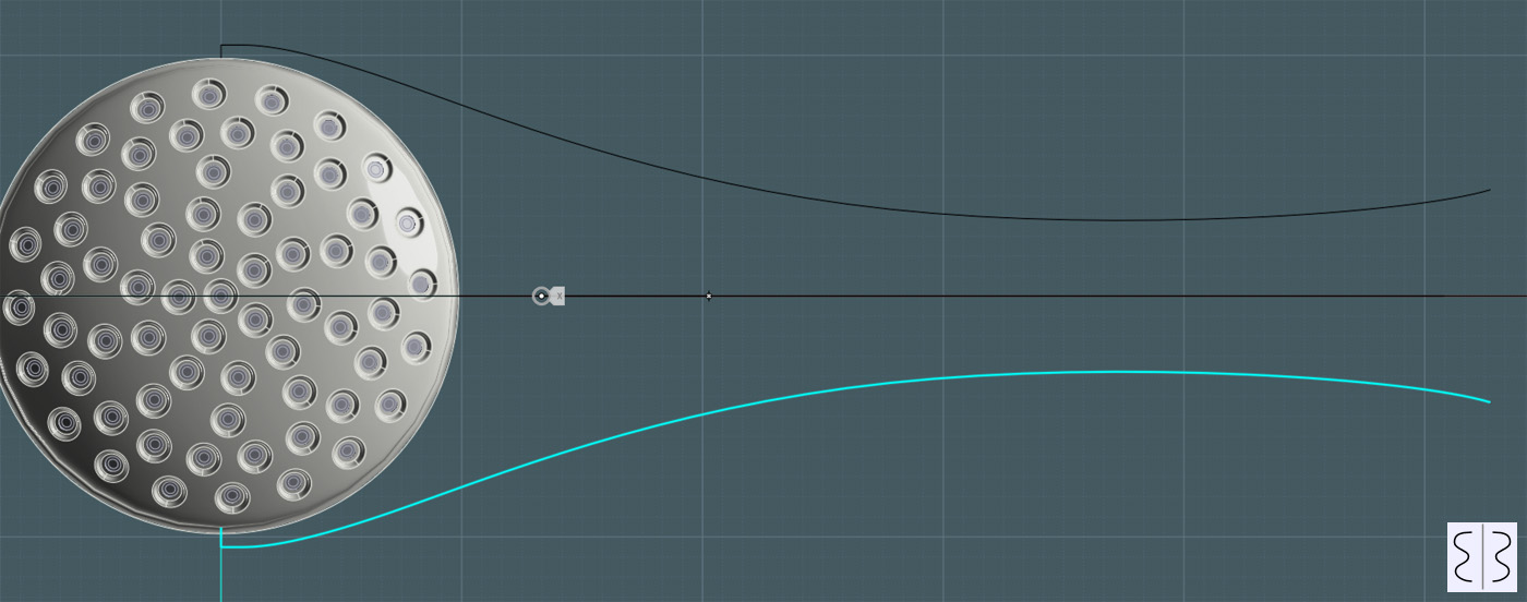
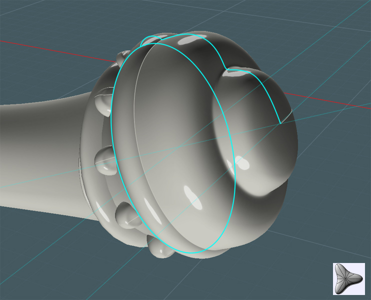
7) Next, I used the same ellipse tool at the other end of the rail set.
Because these were placed at an ad-hock angle, the bottom of the ellipse did not touch the curve-end. I suggest just moving the end point on that rail to touch the ellipse.

Nice...
8) Networked the combination of the rails and rings. All I needed was the two end rings in place and it saw the entire run.
Note: If you get strange results in the middle, using more rings throughout the course will give you more control.
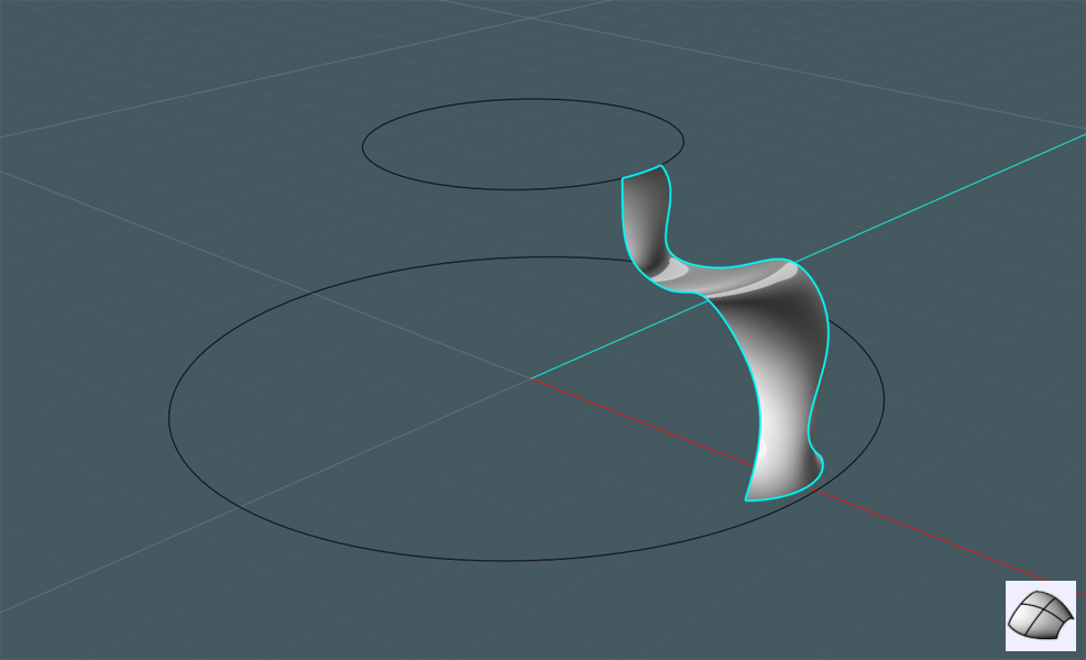
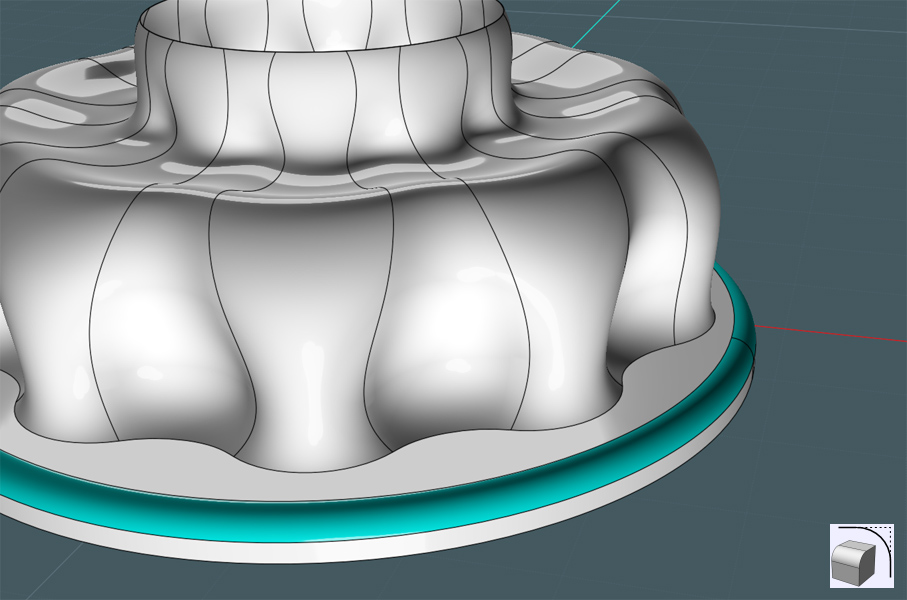
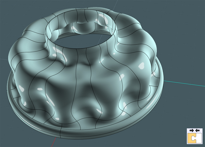
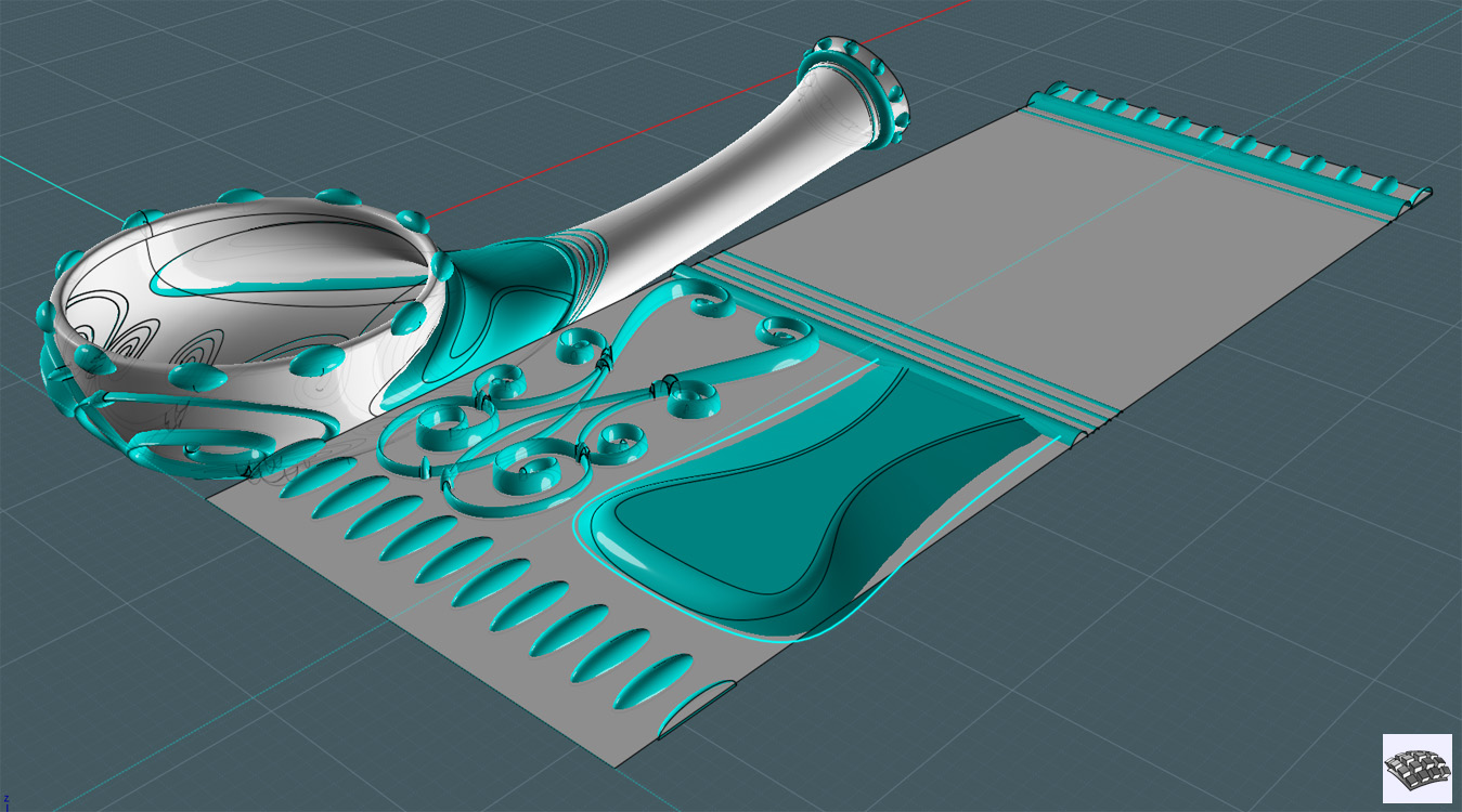
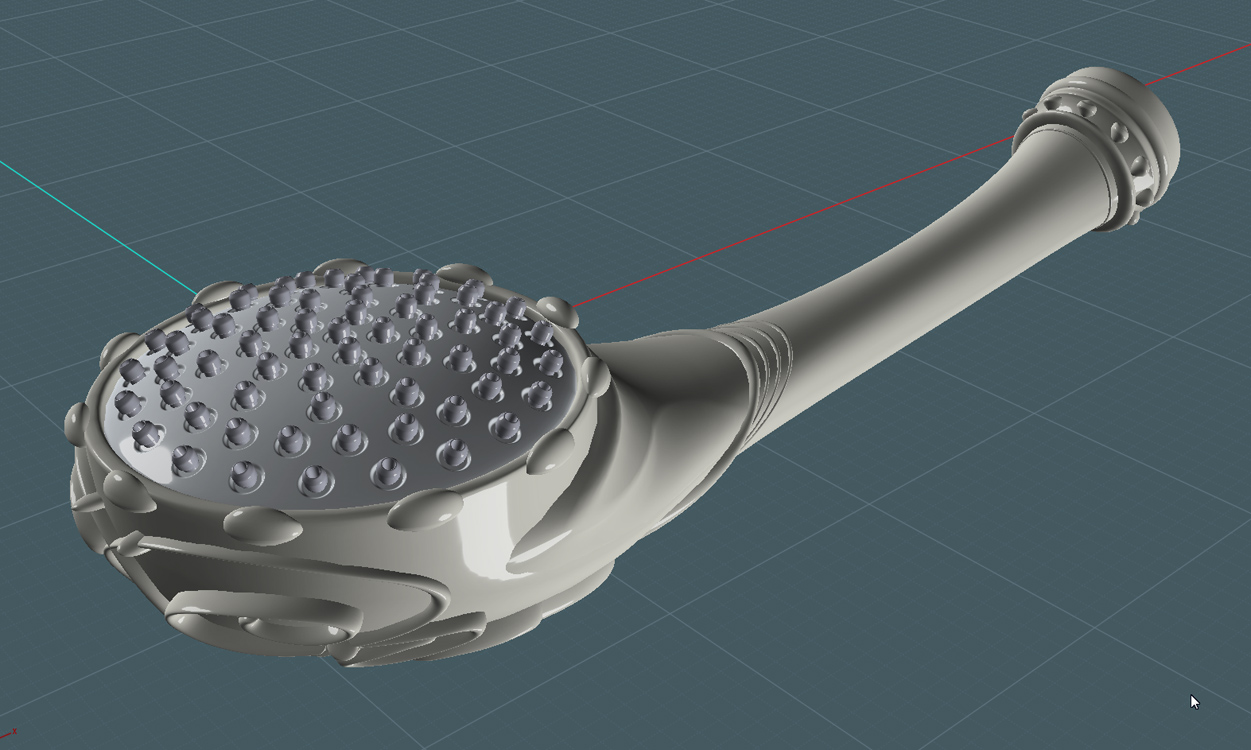
Let's put some detail on that bad boy using the MoI V3's Flow tool!
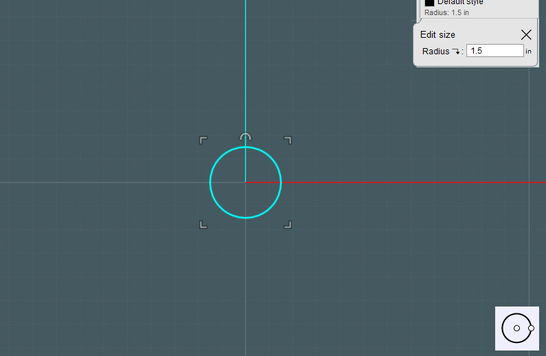
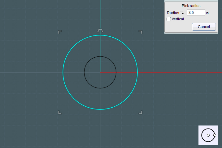
9) Draw a simple reference plane.
Note: Show Points on the plane to make sure that the corner control points are in the corner and not a half mile down the street as shapes are made with the Planar command.
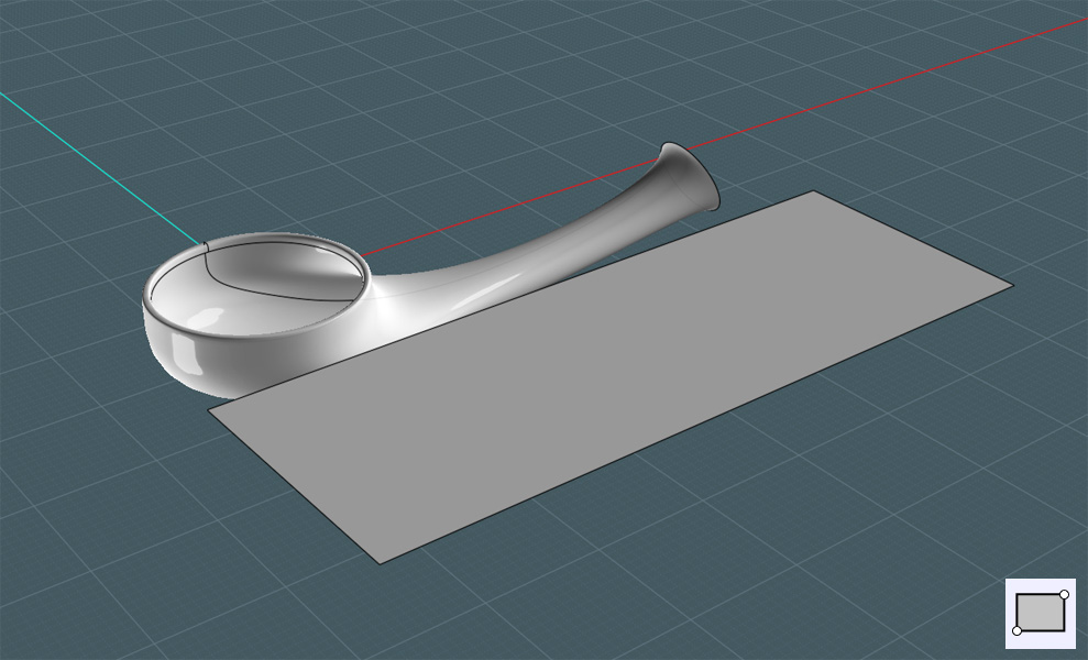
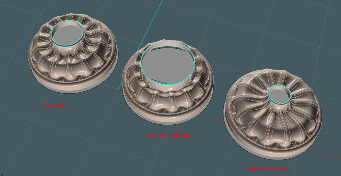
10) Now use the V3's new "Decoration Spray Tool" to add some neat elements...
C'mon silly... This is where you put your own toppings on it like a homemade pizza! ;-)
This tutorial cannot get into the detail of how I made those elements
- but if you like, here is the flourish shape:
http://www.mediafire.com/file/upoj1nkvnnigxtx/flourish_shape_01.3dm
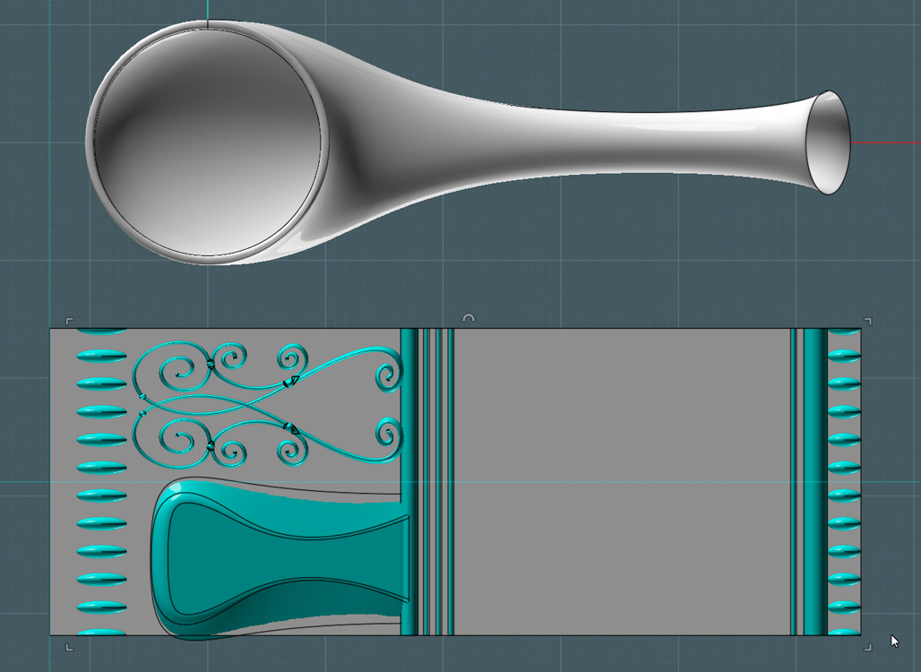
11) Used the Flow tool.
Here's a note on my placements: The seam on the Network mesh just happened to end up on one of the sides.
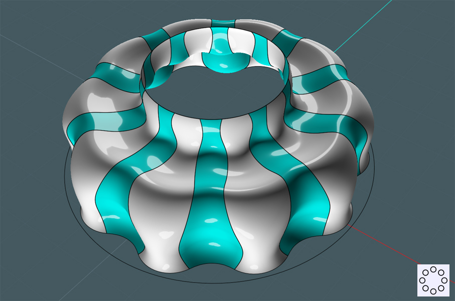
I divided the reference plane into two parts. One would be Flowed to the bottom and the other to the top as the objects were "rolled on".
The big technical aspect to consider when using the Flow tool is that Flow will match reference surface to target surface. And if the points arrangements on one surface is in a warped pattern that is not "grid-like" then the object will be warped to follow suit.
The points on the shower handle body were not straight, but had a strange warp to them. This forced all the objects on the reference plane to skew in accordance to the target surface's point-grid positions.
Remember when I said above that adding rings to your mesh would add control? That may have also "straightened" up much of the grid in the target surface as well.
But I played around with the arrangement a little until it looked good enough.
Working with the new Flow command is an art form within itself. It takes a little practice and understanding, but can become a powerful tool in NURBS modeling.
Step 1 - Select the objects to Flow.
Step 2 - Select the reference surface. When choosing this surface, keep in mind [where] on the surface you are selecting as you will need to match that orientation on the target surface.
Step 3 - Select the target surface. Pick a place on the target surface that will best match the orientation of the reference surface to your objects.
Step 4 - Preview... if the objects are on the wrong side, select the "Flip Normals" option. Done.
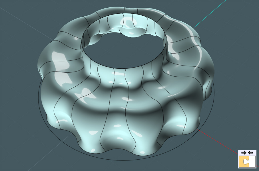
Kind of funky... BTW, don't expect to Boolean anything with the main surface the objects are flowed too. The underlying points are too convoluted.
It's best to use a copy of the reference surface to make a "new" surface with the object already attached.
Kind of neat...
Objects are very warped, but it will work for this tutorial.
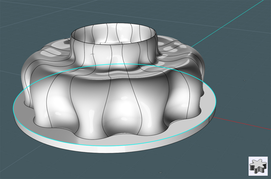
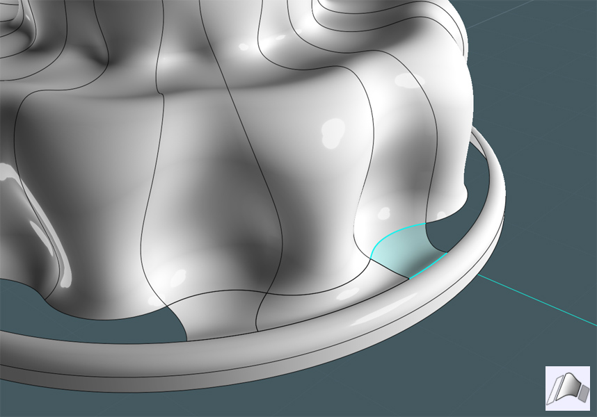
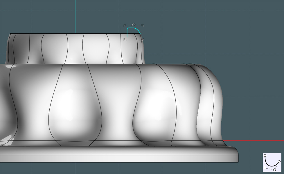
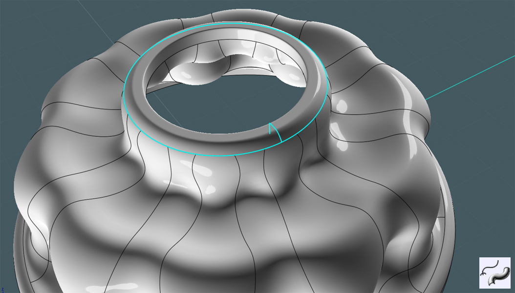
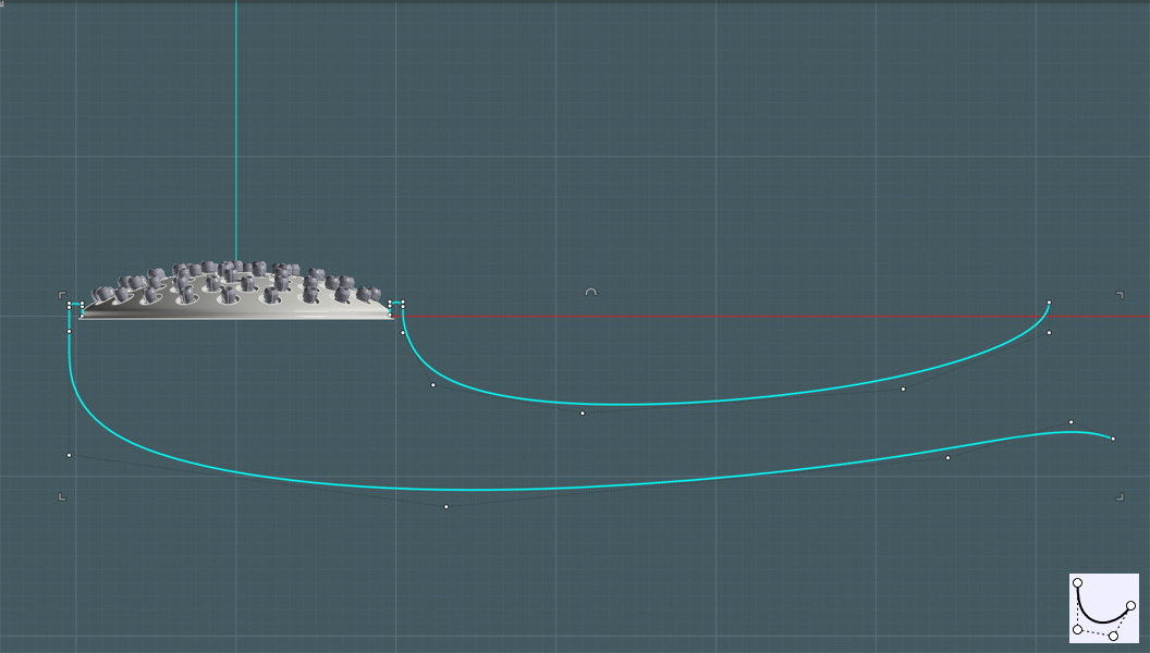
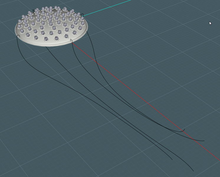
I need to finish out the bottom part of the shower handle by adding some kind of end where the water supply hose will attach.
There are two things about the arrangement here that makes it a slight challenge: One, the circle on the end is not perfectly flat or "circle". Two, it's oriented at an angle.
I need to make a revolved shape, but regular revolve might not match the imperfect circular end.
I could use a sweep of a profile along the end circle as a rail, but I may get a pinched result at the end as sweep was not meant for perfect revolves.
The easiest thing to do is Revolve by Rail.
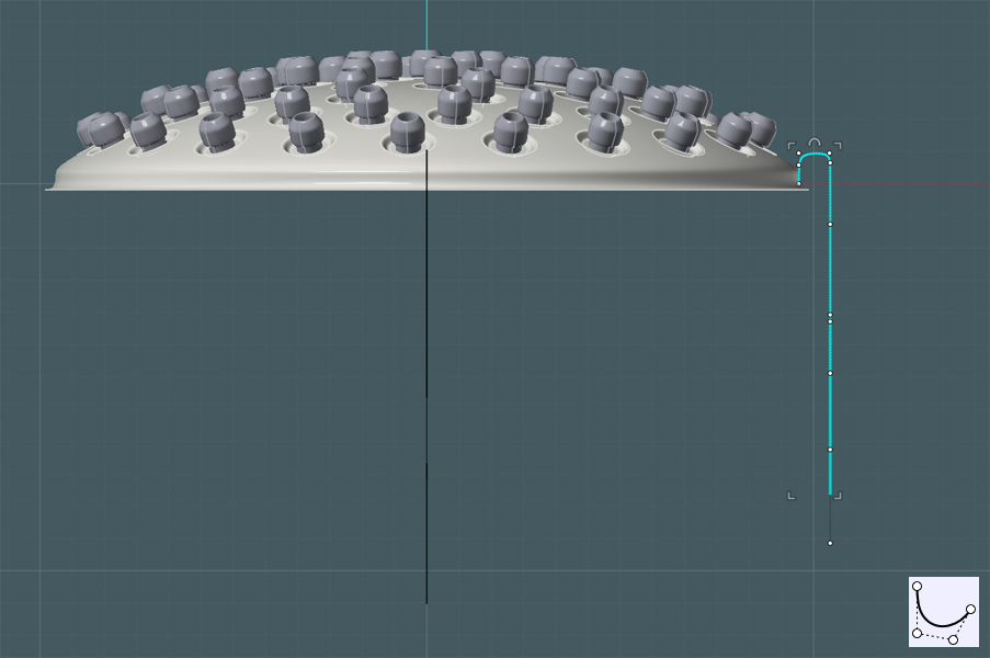
12) To get an axis reference from the circle, I'll make this extrusion first, and then use it's ends to find the center with some construction points.

13) Delete the extrusion object and draw a revolve profile shape.
14) Revolve by Rail to make the object.
Now matter what you do, Revolve by rail will only make a flat bottom shape that will not match to the imperfect rail shape it followed...
A Sweep would have done this, and the result would have been nice, if I would have thought to put a small circle at the other end for sweep to follow... ;-p
None the less... I moved the revolved shape apart from the end of the network mesh and
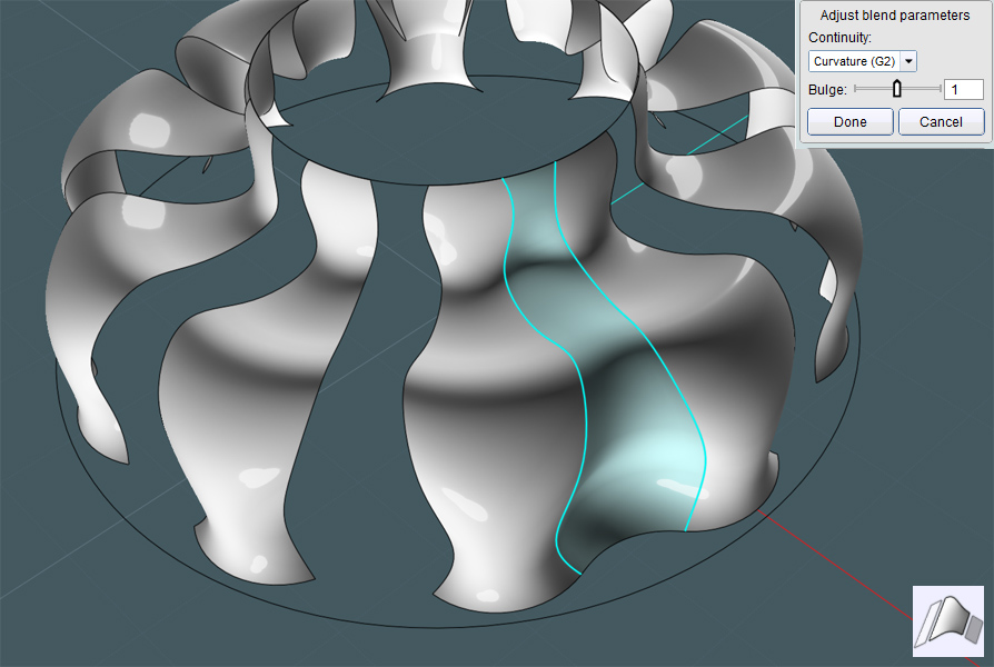
15) Blended the two edges together.
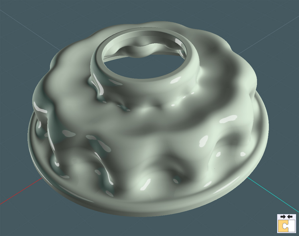
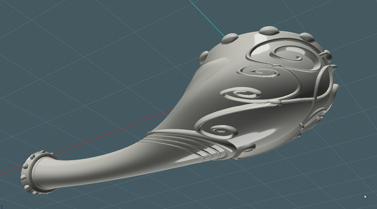
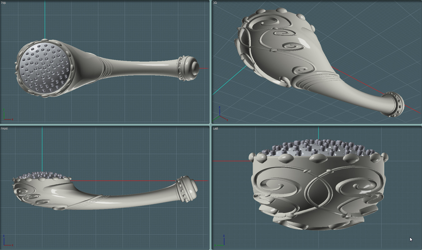
Here is a shot of the final hand-held portion of the shower head assembly.
This will look nice when rendered in antique brass!
Here are a few more views.
---In Part Three: The remaining water hose and adjustable wall mounting parts will be created. And a nice render to follow.