Majik Tutorial: Shower Head
 1-20  21-37

Previous
Next
 From:  Rich_Art
4673.21 In reply to 4673.20 
[quote] I am from Holland! [/quote]

Really?? That is cool. :-)

Peace,
Rich_Art. ;-)

| C4DLounge.eu | Our Dutch/Belgium C4D forum. Cinema4D R13 Studio + VrayForC4D + UVLayout Pro + 3DCoat
  Reply Reply More Options
Post Options
Reply as PM Reply as PM
Print Print
Mark as unread Mark as unread
Relationship Relationship
IP Logged

Previous
Next
 From:  Mike K4ICY (MAJIKMIKE)
4673.22 In reply to 4673.21 
lol... sorry, movie quote. No, not really. ;-)

Some more recent forefathers were.
  Reply Reply More Options
Post Options
Reply as PM Reply as PM
Print Print
Mark as unread Mark as unread
Relationship Relationship
IP Logged

Previous
Next
 From:  Rich_Art
4673.23 In reply to 4673.22 
ah haha ok. :-) Dus dit kun jij dan niet lezen? LoL

Peace,
Rich_Art. ;-)

| C4DLounge.eu | Our Dutch/Belgium C4D forum. Cinema4D R13 Studio + VrayForC4D + UVLayout Pro + 3DCoat
  Reply Reply More Options
Post Options
Reply as PM Reply as PM
Print Print
Mark as unread Mark as unread
Relationship Relationship
IP Logged

Previous
Next
 From:  Mike K4ICY (MAJIKMIKE)
4673.24 In reply to 4673.23 
Met een vertaler, ik kan! ;-)
  Reply Reply More Options
Post Options
Reply as PM Reply as PM
Print Print
Mark as unread Mark as unread
Relationship Relationship
IP Logged

Previous
Next
 From:  Rich_Art
4673.25 In reply to 4673.24 
hahahahahaha cool...
sorry back on topic. ;-))

Peace,
Rich_Art. :-)

| C4DLounge.eu | Our Dutch/Belgium C4D forum. Cinema4D R13 Studio + VrayForC4D + UVLayout Pro + 3DCoat
  Reply Reply More Options
Post Options
Reply as PM Reply as PM
Print Print
Mark as unread Mark as unread
Relationship Relationship
IP Logged

Previous
Next
 From:  Mike K4ICY (MAJIKMIKE)
4673.26 
Part Four: The Adjustable Shower Bar


This is the assembly rigging that holds the shower head handle and allows it to adjusted for use.
You can also attach other items, such as an adjustable shampoo and soap tray.

It's very basic. Just a bar and two braces to hold it to the wall.
But most of the work will be invested in the fru-fru rococo-ness of the assembly's superficial design. ;-)


First we take the escutcheon cover that was made earlier and place two of them as they would be on the shower wall above the tub or shower floor.


The center hole in the cover was made to be 1.5" d. To make an instant pipe, simply Extrude one of the center circle shapes.
This will complete the brace.


Use construction lines to infer the pipe sizing to create a circle for the vertical bar, (or copy the extruded object).


And Extrude the circle. Any length will do.


Later, I'll be replacing this bar with one having a little more detail.


Here is where you can have a little fun:
Create a profile with your curve and line tools. Then Revolve the shape to make an interesting object to act as the bar and brace union section.


Why not decorate it?
I created a small Sphere in one of the circular areas and sunk it half-way into the object. Then I Circular-Arrayed copies of it.


And to give the decoration a real molded/pressed look I Boolean Unioned the spheres and Filleted the resultant mating edges.


I created a profile shape and Revolved it around the vertical bar.
Inside of this piece would be a nylon friction sleeve and the housing for the friction lock.


Union the two revolved objects together.


Simply Fillet the mating edges to make a smoothed transition.


Okay... There's nothing simple about this. This is my second attempt and the Fillets did not want to take until I re-Revolved a new center shape. You may also try Difference cutting the shapes into sections and Blending their edges.


This bar is adjustable. So there has to be a frictioned tension adjustment knob on the side.
Yes, there are braces that would essentially be fastened to the wall in fixed positions, but there is still a need for lee-way with attaching extras.
And this model illustrates the principal of the design.

Create a couple of circles from the center of the vertical bar.


Make a Projection of the larger circle to the side of the shape.


I trimmed a larger circle out of the main object's side and made the inner circle Planar.
Yes, I want to Blend the surface edge of the hole in the side to the edge of the planar circle.
Because the main object has a seam line running through the middle of the hole, I Trimmed the edge curves with "Add-Points" to create two matching edge sections.


I Blended the edges and then joined all associated surfaces.
As you can see, there is now a smoothly made protrusion from the main object's side.


I did a similar procedure to create a custom inset.


Here, I'll make a knob to go on the side. It will have a floral look to it.
So, Let's create a small circle and Circular-Array it around a center point making sure that the circles overlap.


Boolean Union the circles and delete the remaining inside shape.

Fillet will smooth out the sharp creases...


Now we will use MoI V3-Beta's new "Majik Cloud and Rainbow" maker... You do know about it, right? ;-)

Just kidding! A little Photoshop to show effect.
Here, the floral shape was copied and arranged - and a few circles were also added.

The image below illustrates that (following the color transition:) a Loft was then performed with profile rings that were selected in the order by which the surface was created.
In this example, from top to bottom. The Loft command was set to the "Loose" setting, and a neat floral shape was produced.


A Revolved profile completed the tension knob object. An extruded circle was made from the bottom to create a bolt.
All surfaces were Joined together.


The tension knob was rotated, and moved to alignment with the main object.


A copy of the entire brace and union set was copied to the upper part of the vertical bar.


As you can see - this model can later be recycled to make decorative walk-way rails. Yes mates - Queuing in style!

Now to cap the bar ends:

A profile curve is made and Revolved using the center snap point of the vertical bar's bottom circle for the axis.


I made a broad curved space to add detail like fluting.
I made a Freeform curve to mimic the edge of the revolved surface.


I played around with a few different shapes to work with, but settled on Sweeping two profile ellipses to the rail curve.


If you place the profile shapes for the Sweep below and away from the imaginary boundary box of the rail curve then MoI will take those shapes, one by one - as arranged and performs a Sweep merging the shapes along the path.


Here I then did three things:
1) I moved the Swept shape so that it sunk a little into the revolved object.
2) I performed a Circular Array to the shape around the revolved object.
3) I Boolean Differenced the main revolved object away from the Swept shapes, leaving curved surfaces.


You can simply Boolean Union the Swept shapes to the Revolve shape - then Fillet their edges.
But the Fillets didn't work........

I needed to make edge Blends instead.

I wanted to make the shapes smaller. So I created a profile curve to act as a cutting shape.
Working in a side view was good for visualizing exact placement.


I revolved the profile with the ends capped and trimmed that resultant shape from the curved surfaces.


I failed to show a few steps here, but needless to say, this is up to your own discretion.

I created a larger (or offset) shape that was also circular-arrayed, Projected and Trimmed from the revolved object's surface.
I then Blended the surface edges of each object.
This gave me a more smooth transition between features.
This was not without trouble as well. I had to both Trim and "Merge" many of the curve segments that were broken up on the edges.


Just simply copy/flip the cap section to the other end of the bar.


Whew!
I had a bit of trouble getting this part done... My home PC had a few technical glitches.
Both a video card and power supply unit had to be replaced! Noooo... I believe the PSU might have ruined the vid card,
or that lightning got both at one time... who knows.
But most likely - it was a lethal combination of NEGLECT and the caking of dust! The poor ventilation and 24/7 operation may not have helped much either. :-o

None the less -


In the next one or two sections I'd like to finish up the shower head model with some extra details being added to the frame.
And also, the modeling of the helical metal water supply hose.

Then later a few good renders after I model up some control fixtures.


Please Visit http://k4icy.50webs.com/tutorials.html for more Tutorials!

EDITED: 29 Nov 2011 by MAJIKMIKE

  Reply Reply More Options
Post Options
Reply as PM Reply as PM
Print Print
Mark as unread Mark as unread
Relationship Relationship
IP Logged

Previous
Next
 From:  Marc (TELLIER)
4673.27 
Cool tutorial, thanks Mike!

Marc
  Reply Reply More Options
Post Options
Reply as PM Reply as PM
Print Print
Mark as unread Mark as unread
Relationship Relationship
IP Logged

Previous
Next
 From:  Frenchy Pilou (PILOU)
4673.28 
works also for curtain rod! ;)
  Reply Reply More Options
Post Options
Reply as PM Reply as PM
Print Print
Mark as unread Mark as unread
Relationship Relationship
IP Logged

Previous
Next
 From:  Rich_Art
4673.29 In reply to 4673.26 
Respect.. really cool design. Thanks again for the tutorial..

Peace,
Rich_Art. ;-)

| C4DLounge.eu | Our Dutch/Belgium C4D forum. Cinema4D R13 Studio + VrayForC4D + UVLayout Pro + 3DCoat
  Reply Reply More Options
Post Options
Reply as PM Reply as PM
Print Print
Mark as unread Mark as unread
Relationship Relationship
IP Logged

Previous
Next
 From:  Mauro (M-DYNAMICS)
4673.30 
Thanks for sharing..plumber Mike...!!
  Reply Reply More Options
Post Options
Reply as PM Reply as PM
Print Print
Mark as unread Mark as unread
Relationship Relationship
IP Logged

Previous
Next
 From:  Mike K4ICY (MAJIKMIKE)
4673.31 In reply to 4673.30 
Thanks guys!

> "plumber Mike...!!"?
How 'bout "Pipe Master Flex"? ;-)


This bathroom scene is taking waaaaaaay too long... I can't wait to model other non-plumbing items: vehicles, planes, radios, buildings and more... ;-)
  Reply Reply More Options
Post Options
Reply as PM Reply as PM
Print Print
Mark as unread Mark as unread
Relationship Relationship
IP Logged

Previous
Next
 From:  Mike K4ICY (MAJIKMIKE)
4673.32 
Part Five: Accessory Tray

One important piece of equipment is needed to make a good shower head rig - a useful accessory tray for holding shampoo bottles, soap, razors and the like.
This one will have a tray area just the right size to hold shampoo bottles, and will wrap around the vertical support tube on the rig.
It'll be slightly decorative and made from non-corrosive bronze or nickle alloy.


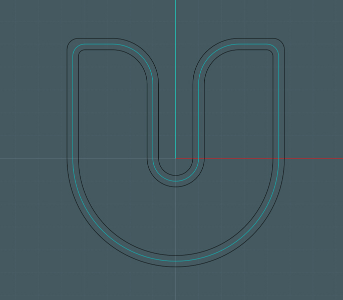
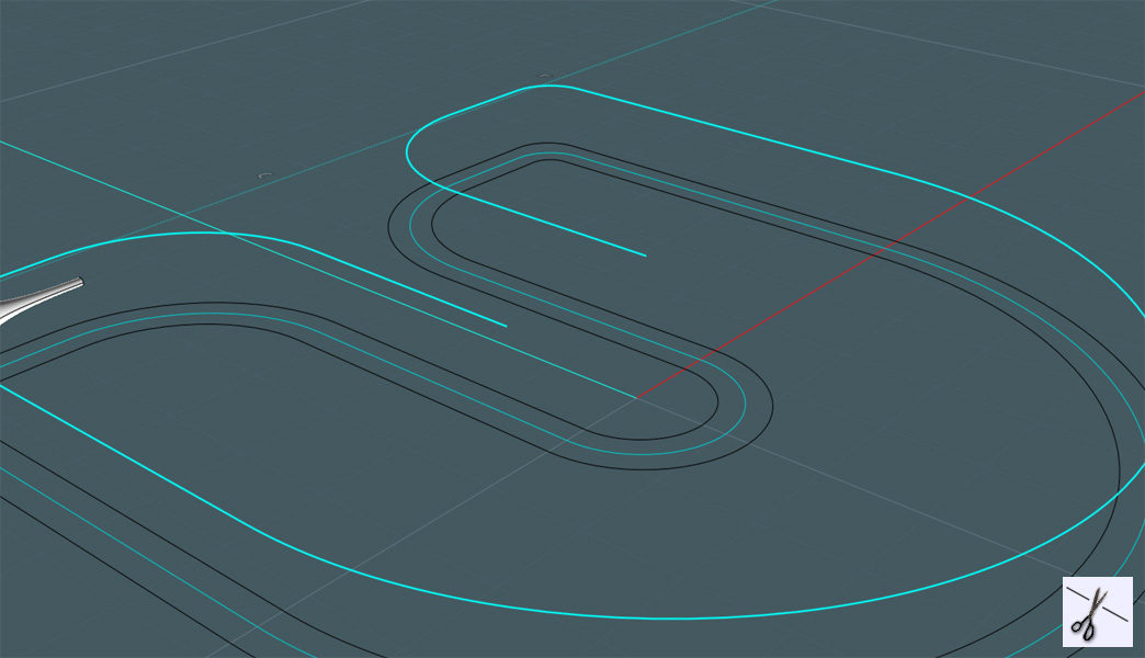
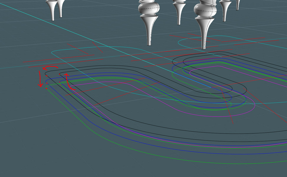
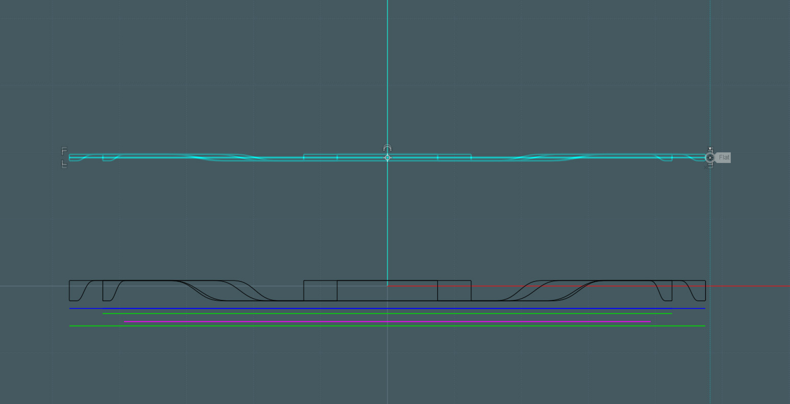
First, I need to establish some shapes in a 2D view:


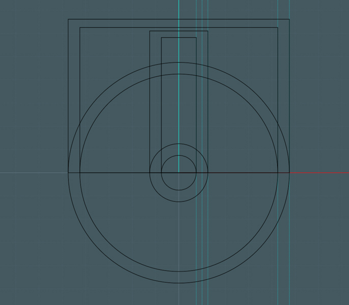
These will define the tray size and exterior retention lip.


Using MoI's easy to use 2D CAD tools, I work with the shapes, using unions and fillets to create the profiles I need:
A 'U' shape is created with the center area the exact size needed to hug around the rig's center pipe.
A center-line profile is made for future reference.


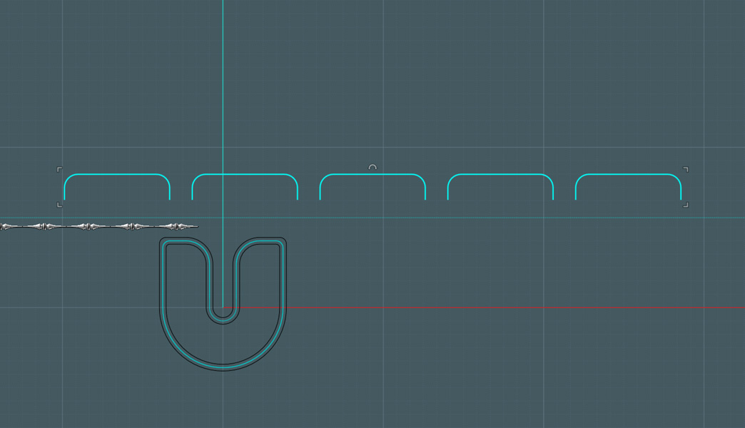
I need to make a decorative rail to help hold the items in the tray.
I start by making a nice profile shape, then revolve the shapes.


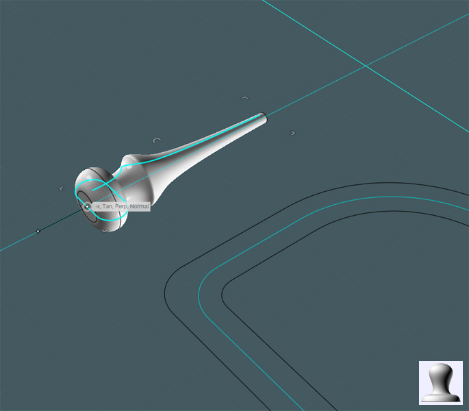
I make mirror copies of this shape to make a bar of some sorts.


The reference profile on the main shape is intended for the rail's construction.


Here, I cut the inside part of the reference rail:


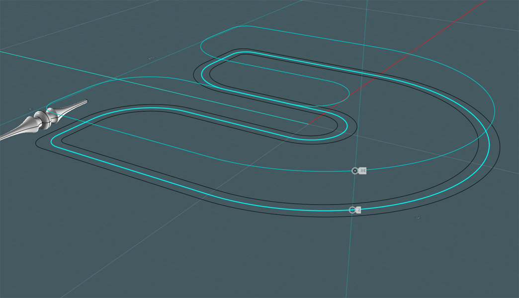
Back in the top view, I draw some shapes that I will make the rail objects follow.


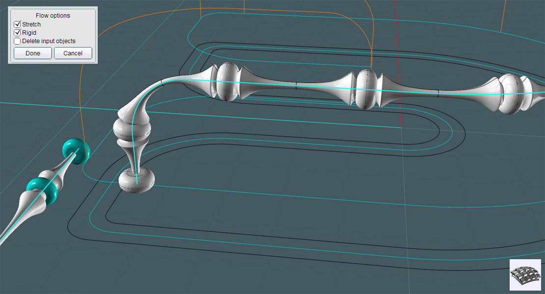
I FLOW the shapes to the reference path:


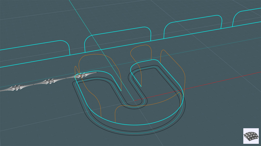
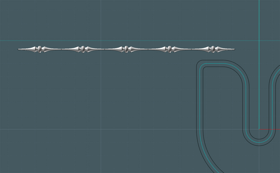
With the rail shapes, I made two sets of shapes, one a tapered shape and the other, a type of bead.
I flow the tapered sets to the new reference paths. Note that this Flow command was set with the "rigid" option OFF.
---Look! I Flowed to a Flow!


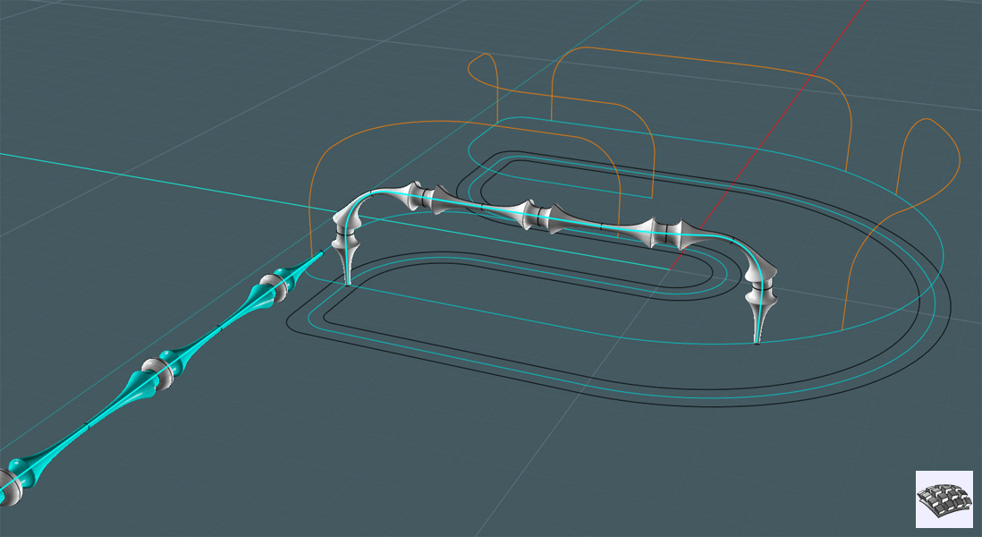
Here, I flow the beads to the same path. A temporary set of beads were placed at the ends so that the flow of each set would match.
This time the "rigid" option was activated to keep the original shape of the beads.


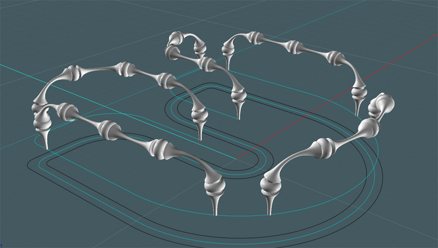
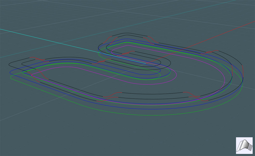
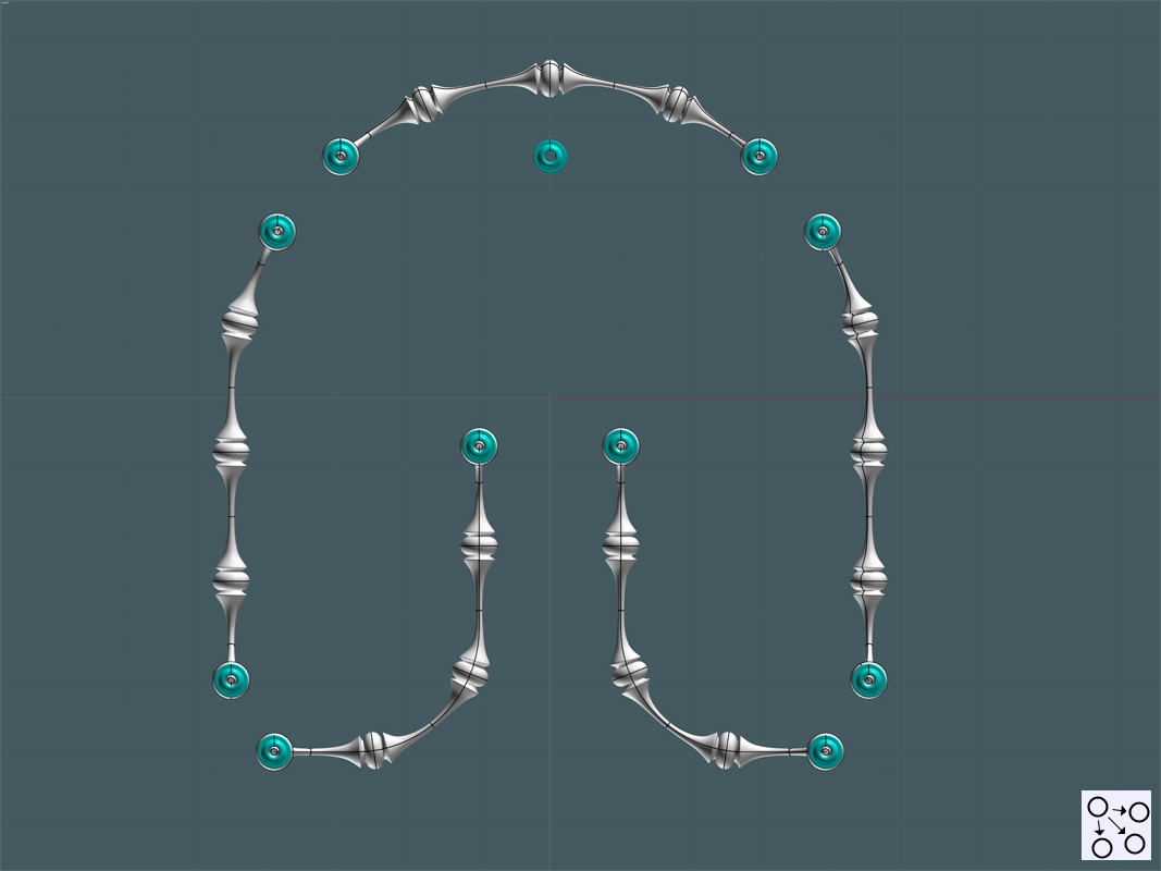
Here is the complete decorative tray rail, completely flowed to the reference paths:


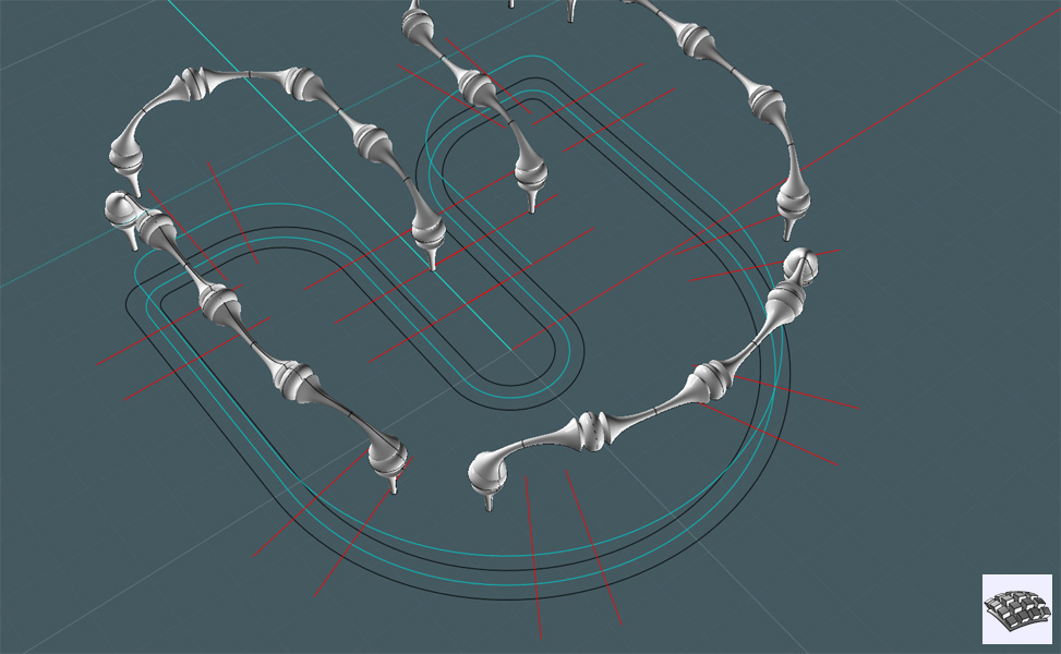
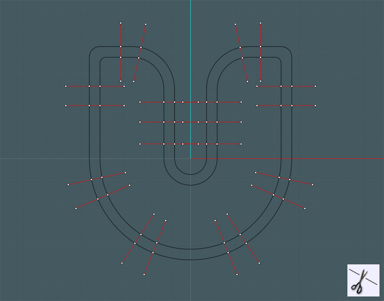
Here, I make some reference lines:


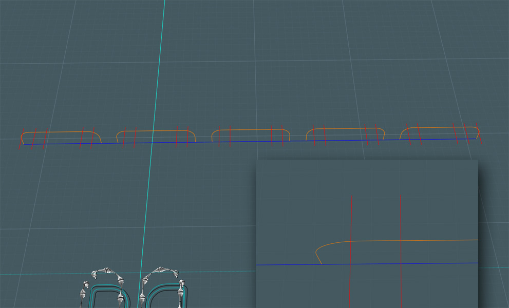
I flow the reference lines to the center reference line.


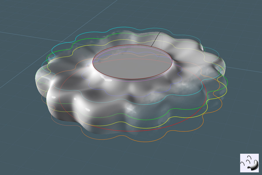
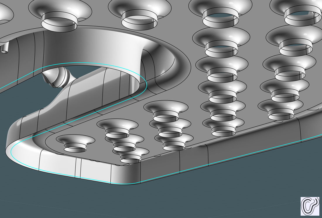
I'll use those references, but first, I need to Loft my profile rings so that they form the tray's ridge lip:


I make copies of those profiles in Z.


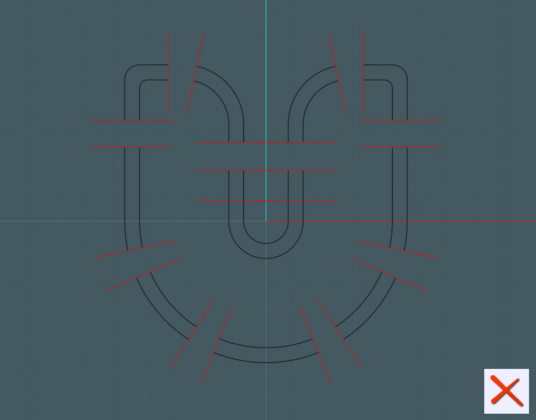
Here, I Trim the reference lines from the top set of profile rings:


And delete what I don't need:


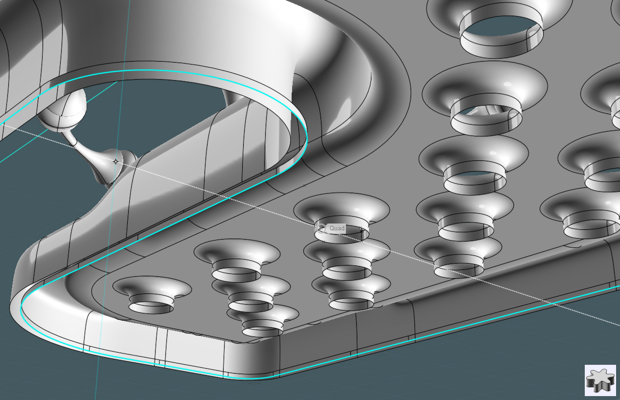
I now move select portions of the separated profile rings - then I Blend their curve ends to make a vertical transition.


To make the Loft work smoother, I need to make a second set of profiles, but with a shorter transition. I use a copy of the new profiles and make a flat copy:
The flat copy is placed slightly lower than the top one.


So when you Loft the sets of profiles, you get the nice ridge shown here:


Now I Blend the ridge surface edge to the edge of a Planar surface made with an offset of one of the inside profiles:


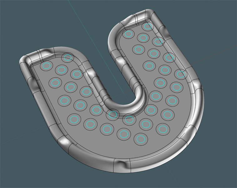
The tray needs drain holes...
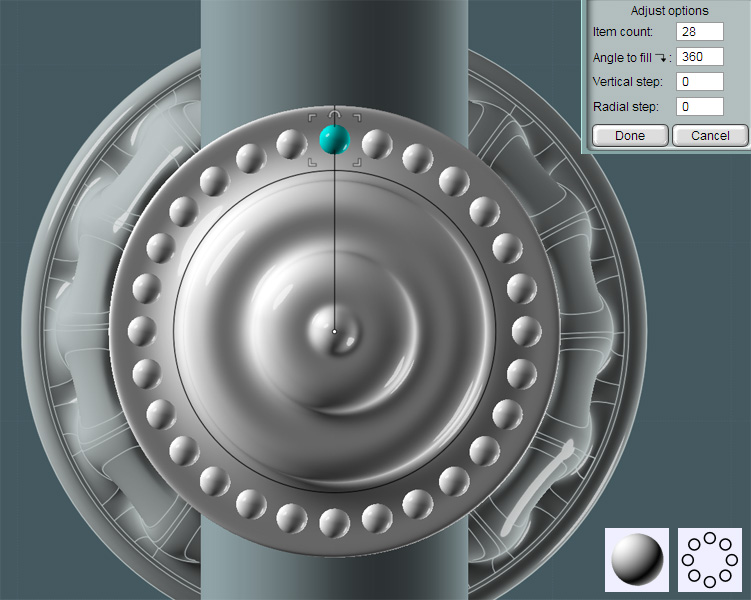
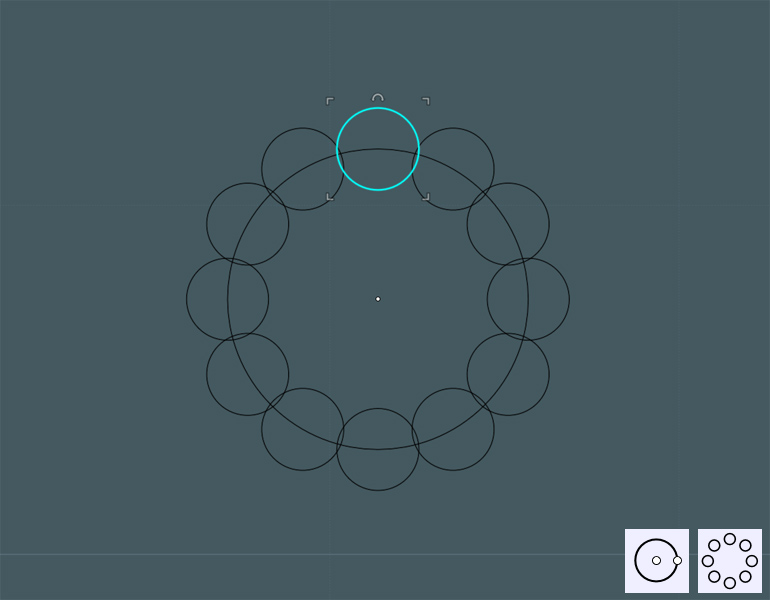
I make some simple circles:


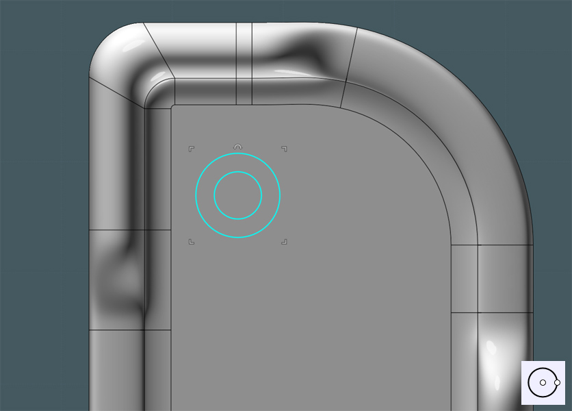
I then use the Array Grid command to make copies. The spacing was wider apart, then I copied the set and positioned it to make a checker board pattern.
I sized and positioned the circles so that they would line up nice on the tray floor. I deleted circles that did not sit complete on the tray floor.


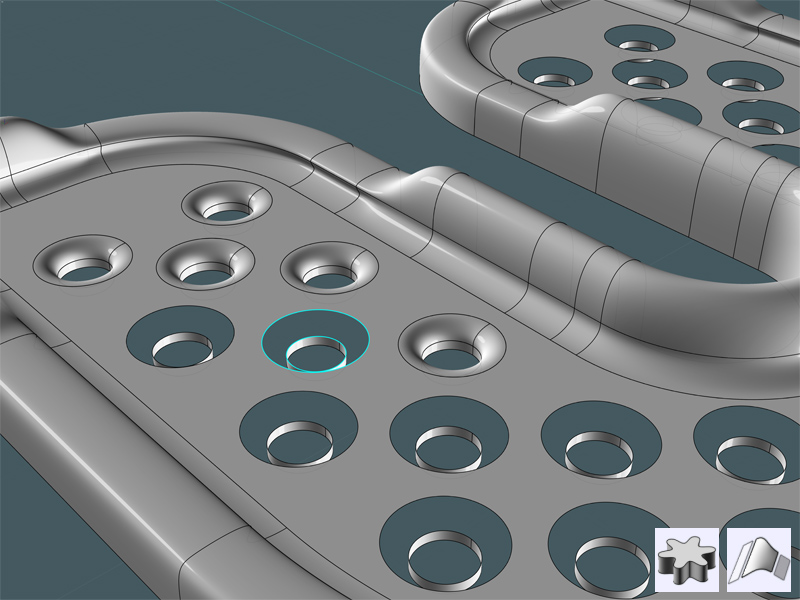
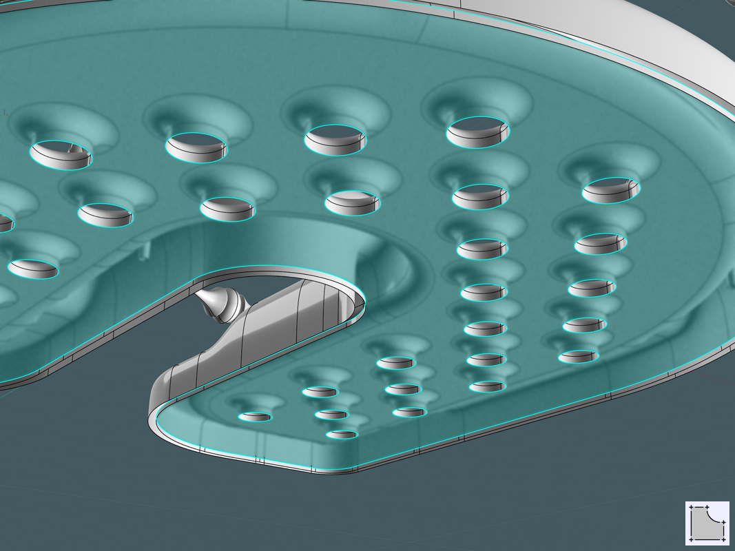
I trimmed the large circles from the tray floor surface:


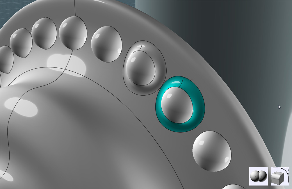
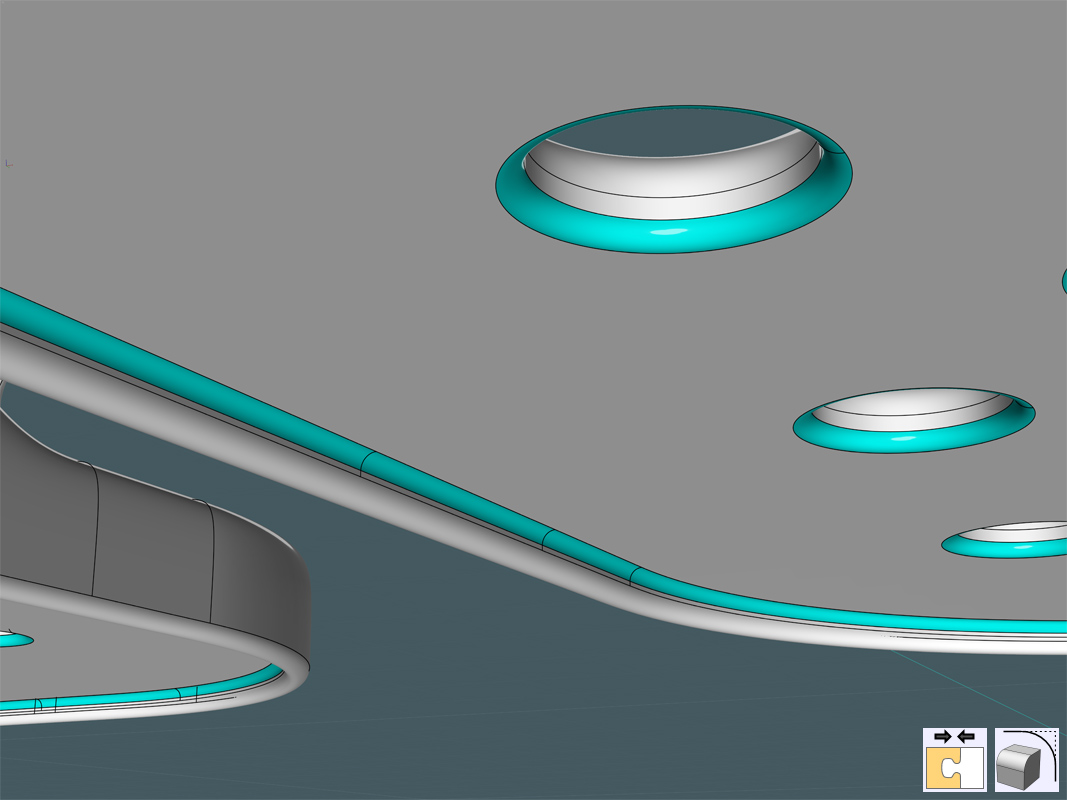
I placed the small rings below the tray floor surface, then I extruded the small rings.
A Blend was made to transition from the edge for the holes to the top of the extrusion.


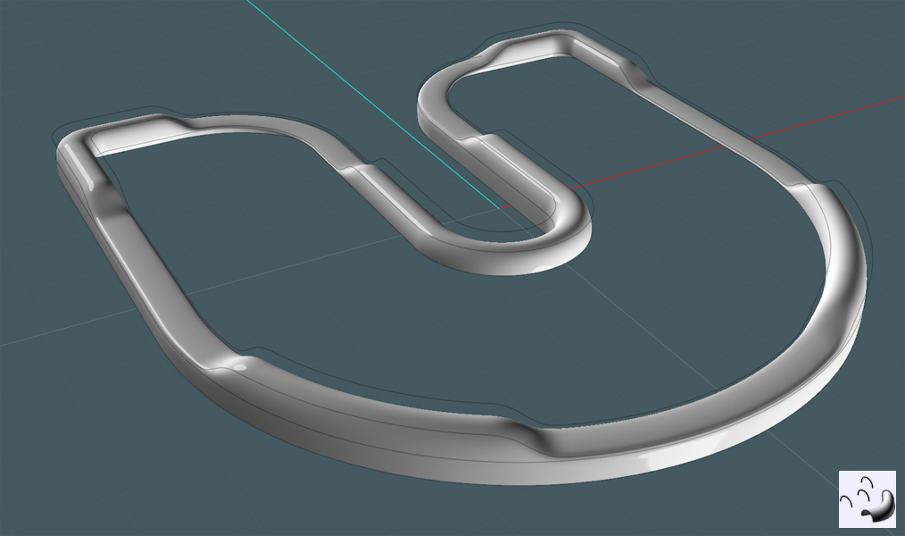
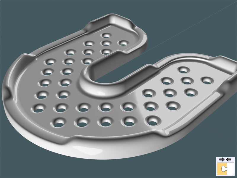
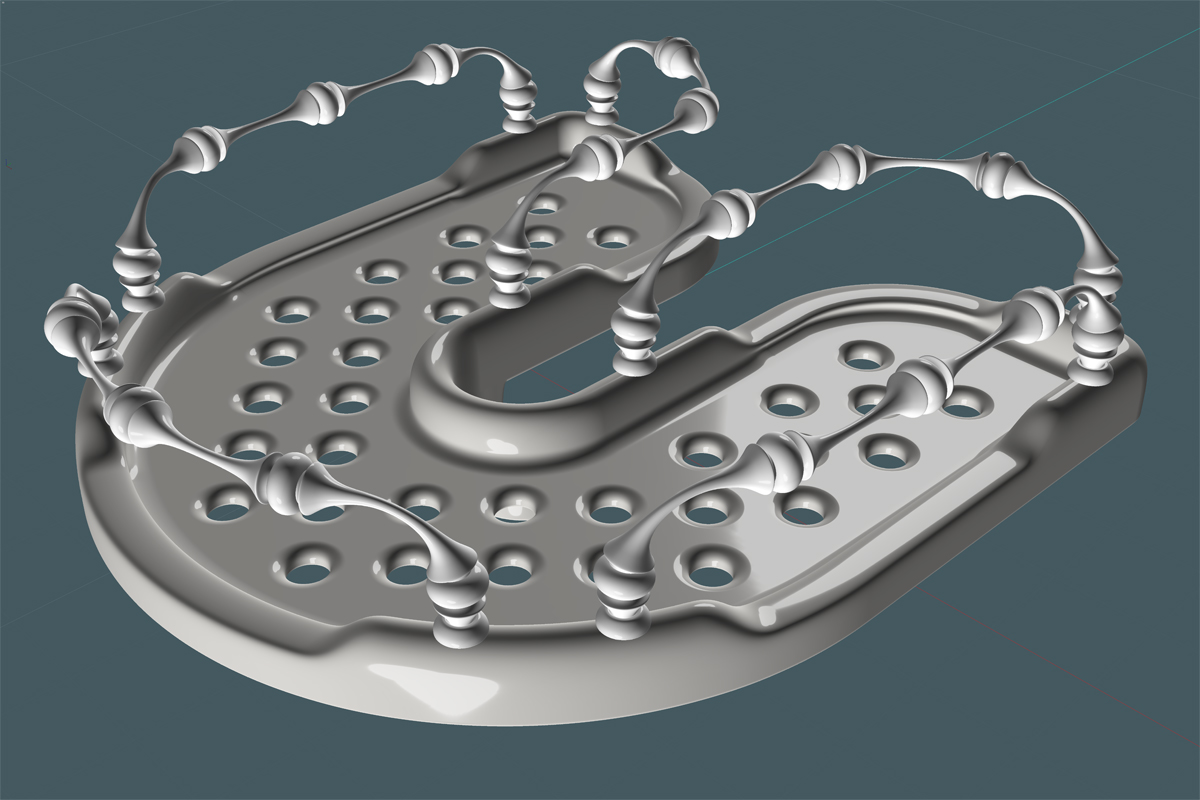
Here is a nice view of the completed tray with all surfaces Joined:


I need to add thickness to the tray surfaces to mimic a real life object.... unfortunately, Surface offset of multiple and complex surfaces is not a MoI's NURBS library strong suit. And understandably, this type of action is better suited for a application based on parametrics, which can negotiate these complex configurations.
So - I'll do the next best thing. Build the other side of the object so that it works.

I make an Offset of the edge profile:


I make an Extrusion of the profile offset:
The Extrusion command will let you snap to a point for inference, so I choose the bottom of the drain hole.


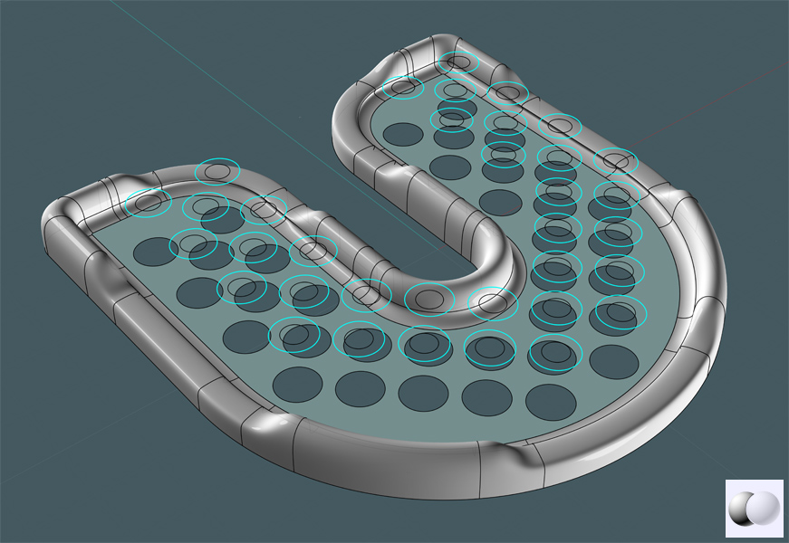
Here, I can now make a Planar surface with the selected rings of the holes and the other edge of the offset profile's extrusion:
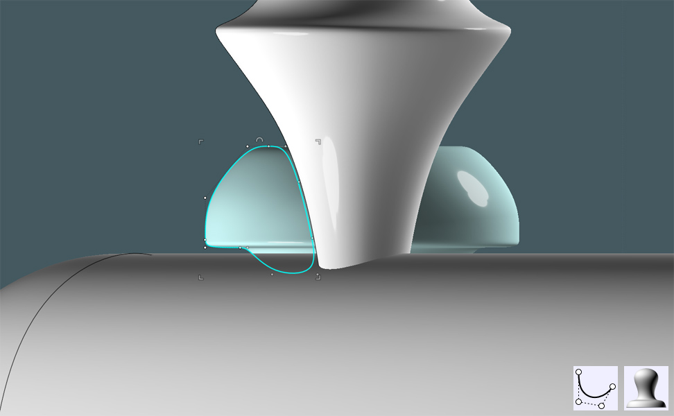
I then give the surface a "frosted glass" material fill ---- Just kidding! A nice Photoshop effect to show the work...


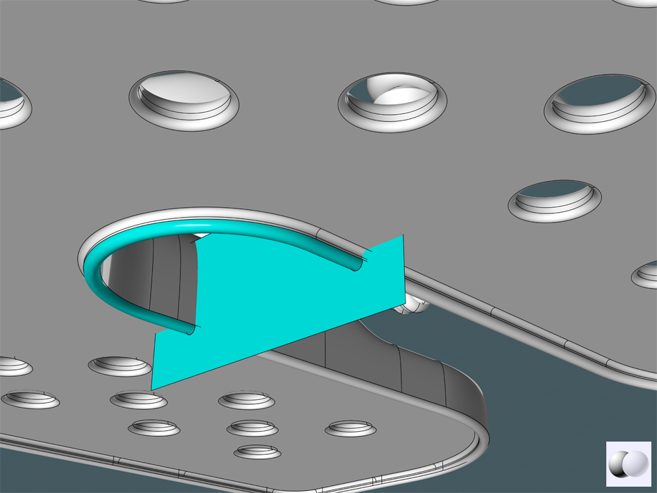
I need to marry the small extrusion of the offset profile to the edge of the tray's ridge.
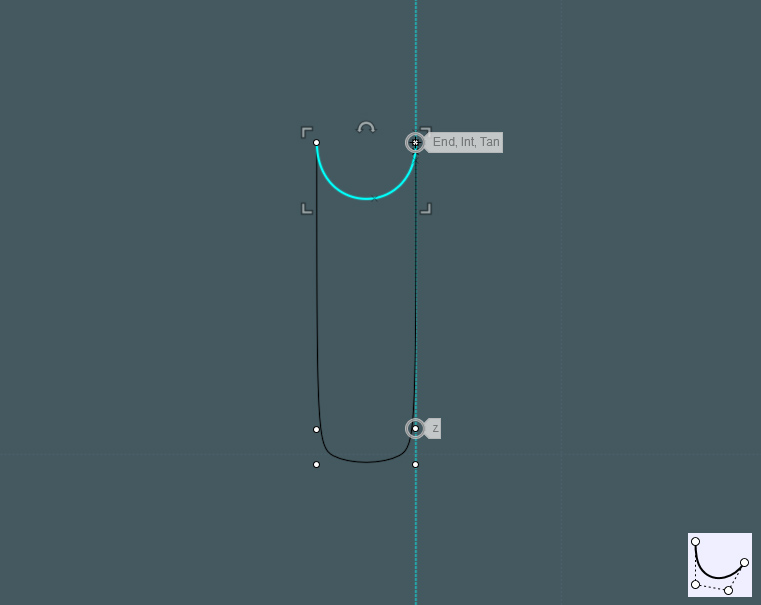
I can either Blend the edges of each surface, or in this case, I make a profile to then Sweep.


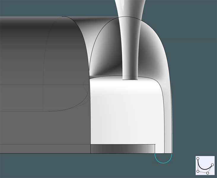
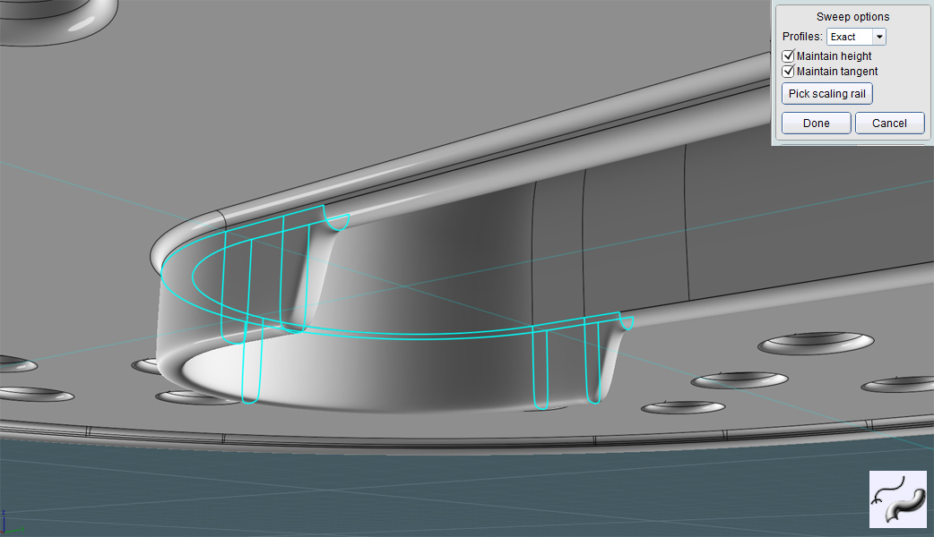
I then Sweep the profile on the rings made by the bottom edges on the tray.
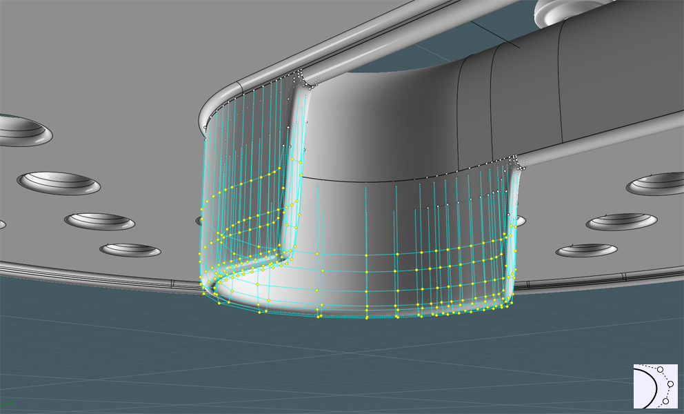
To get the rails, select the surface edge curves, then use the Join command to make a new and separate curve path.


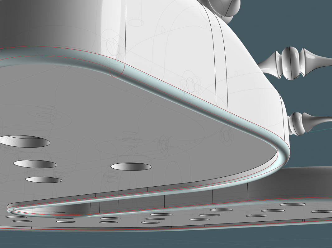
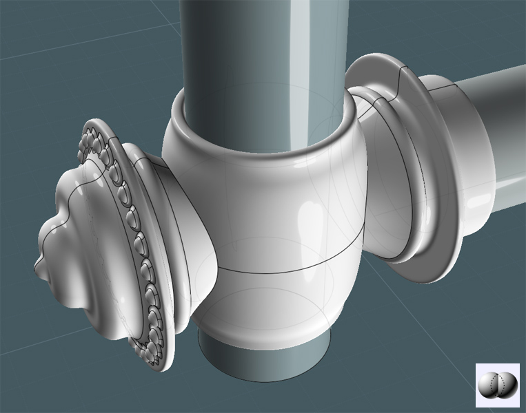
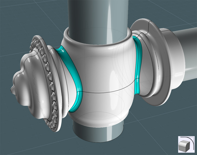
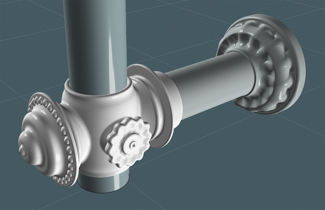
I joined all surfaces, then I Filleted the edges:


At the moment, the decorative tray rail just collides with the tray lip surface.
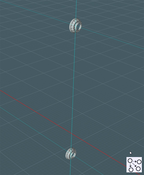
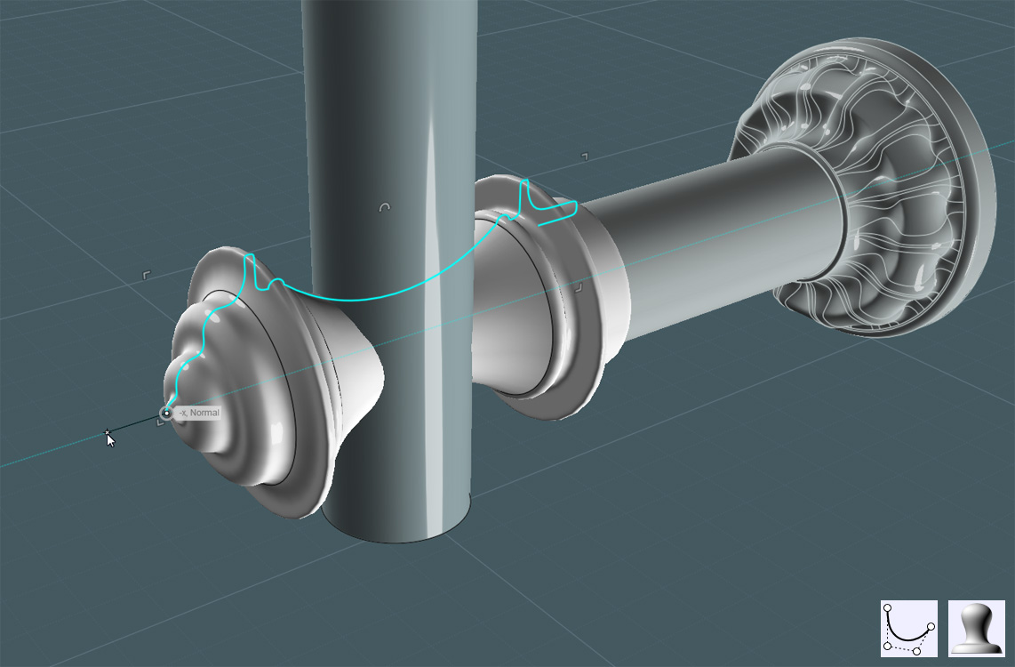
A Revolved profile can make a nice grommet.


Using the Bottom View, I use Copy to arrange the grommets to the end post of each decorative rail set:


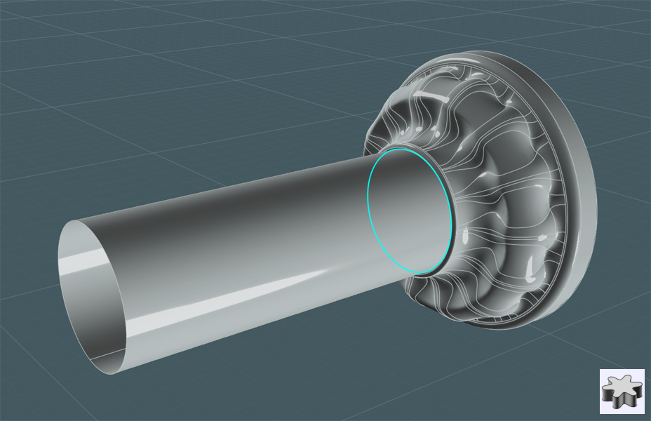
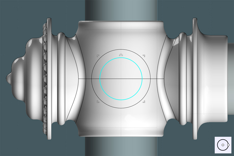
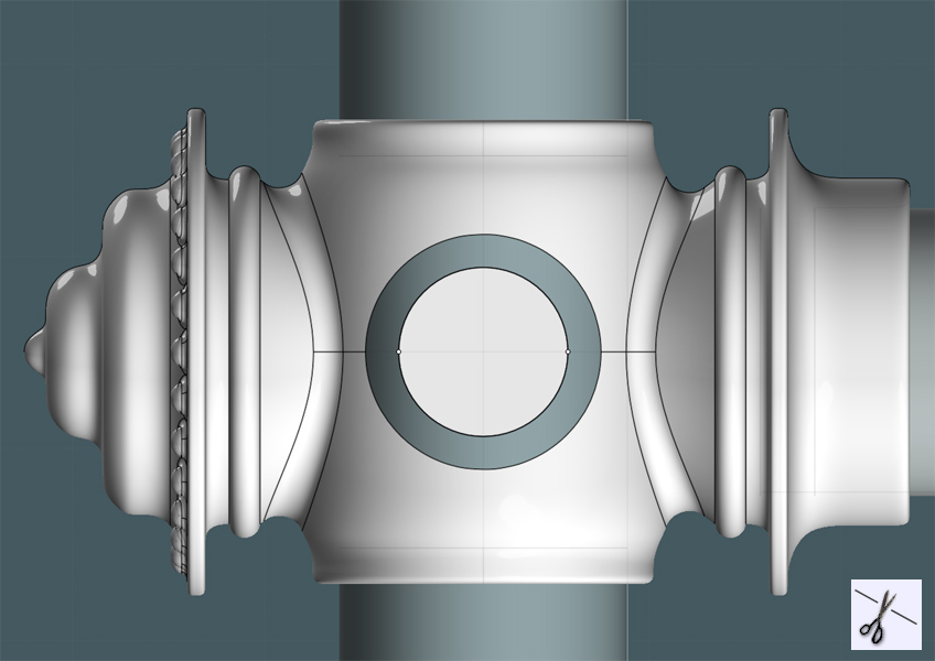
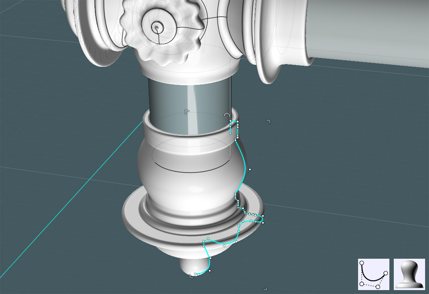
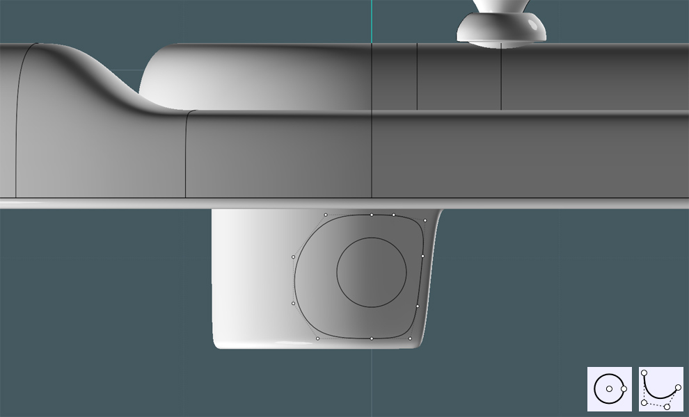
I need somewhere to attach the tray to the shower head rig pipe...
I use an object to trim into the inner portion of the bottom ridge lip.


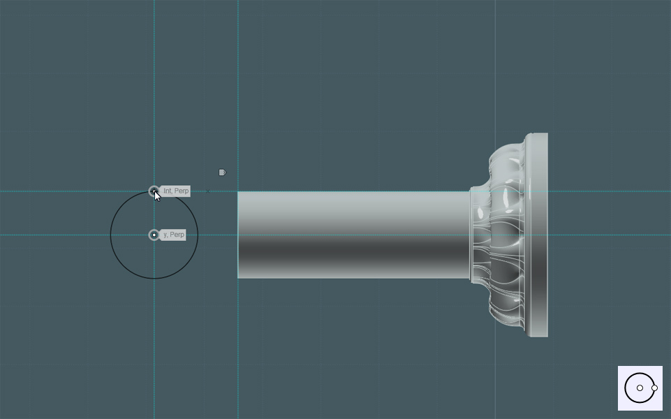
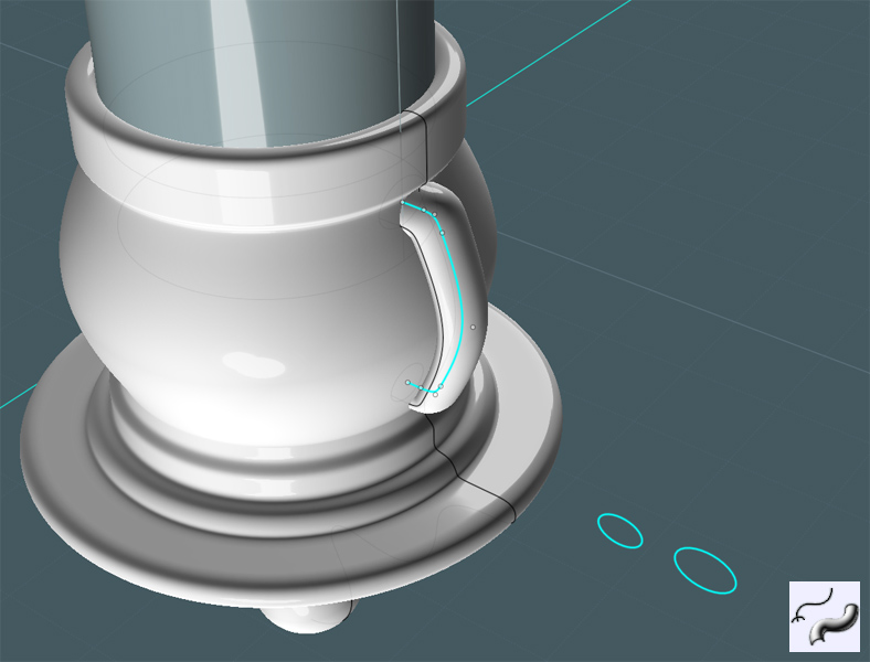
I'll make a taller lip surface. Using the existing lip profile, I'll draw another one:


I use Orient Curve to place a copy at the center location to re-enforce the new lip's shape.
(Michael - I swear, this is the first time I've ever used the Orient Curve tool! :-) )


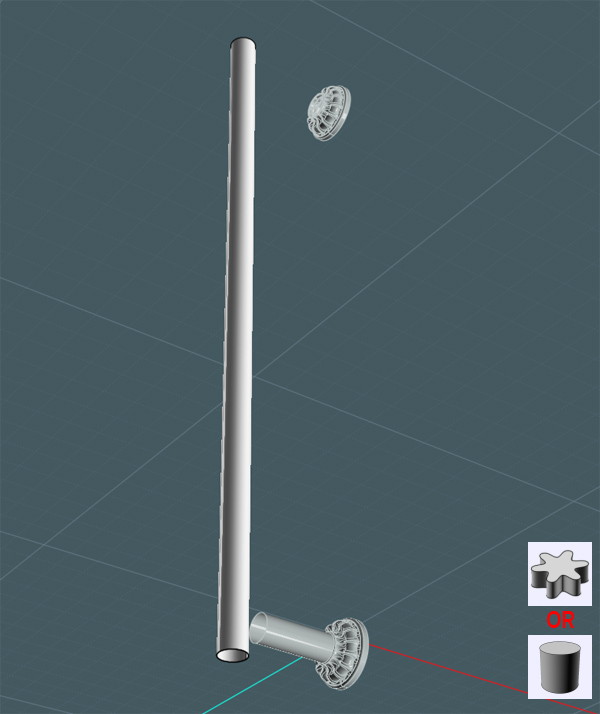
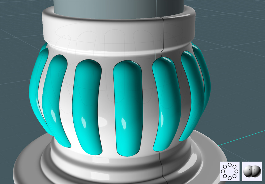
I use Sweep on the profiles and two rails to make a new ridge:


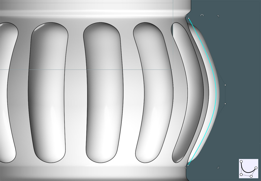
When I looked at the real-world dimensions of the tray, the new lip was too skinny to do any good.
I then turned the control points on and then stretched them until the lip was an inch tall.


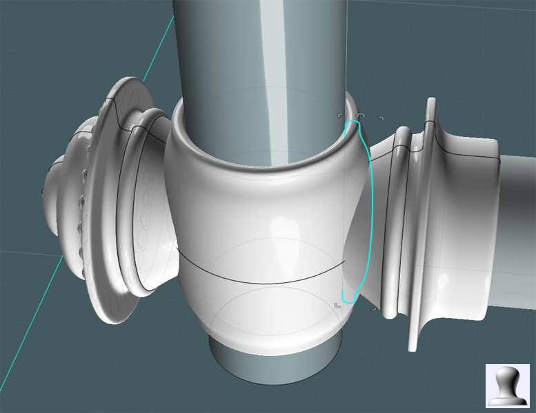
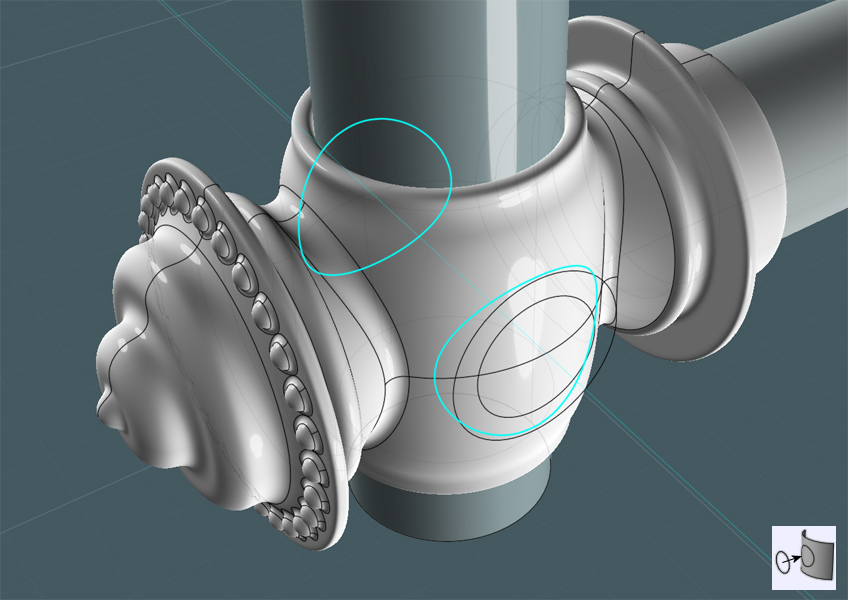
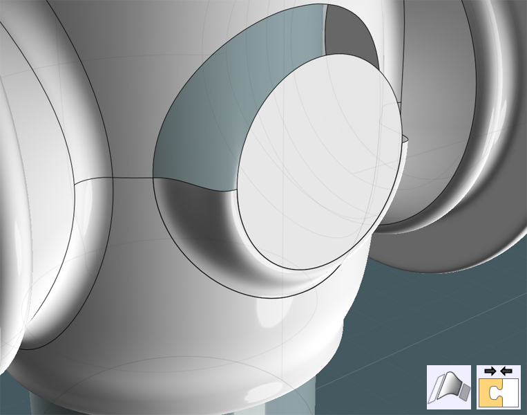
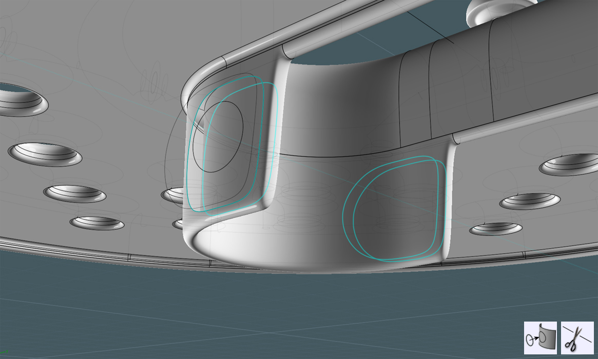
I drew two shapes, so that I can make a bulge area to accept a tensioning bolt.


I projected the outside profile and trimmed the projection out of the lip object:


I Blended the opening edge to a planar of the smaller circle:


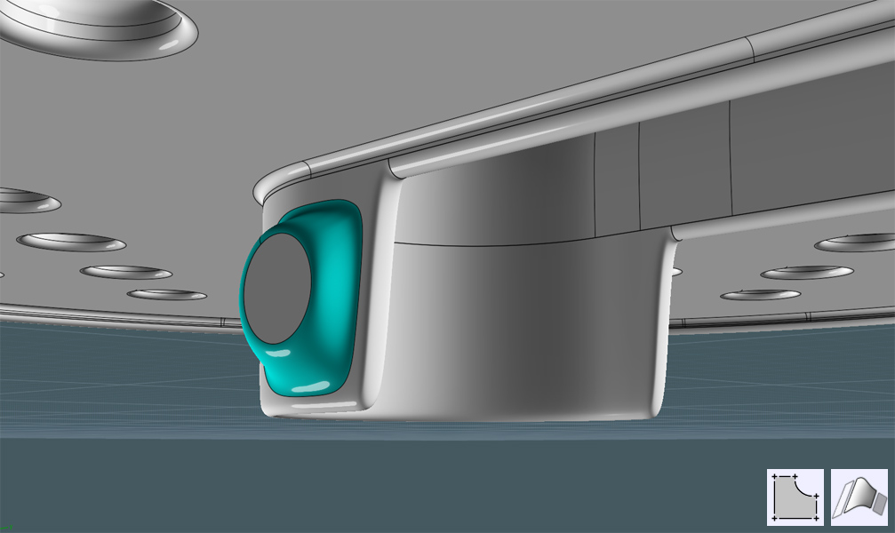
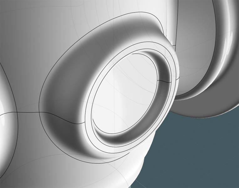
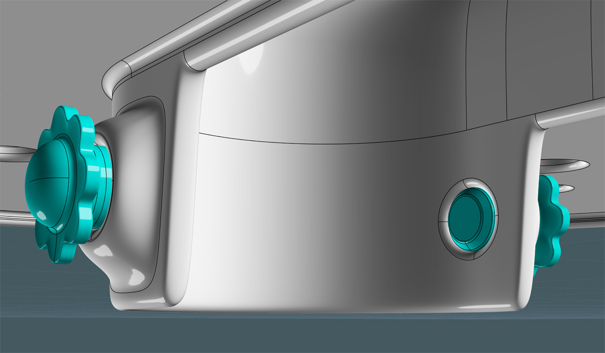
I make ports for the bolts by making a smaller circle, then Boolean Differencing the circle, then Filleting the hole edges.
(Actually, since the object was not a solid, I had to Loft the hole edge rings to make the inside walls.)


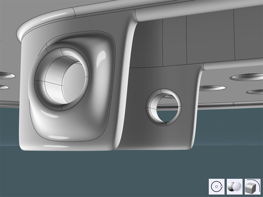
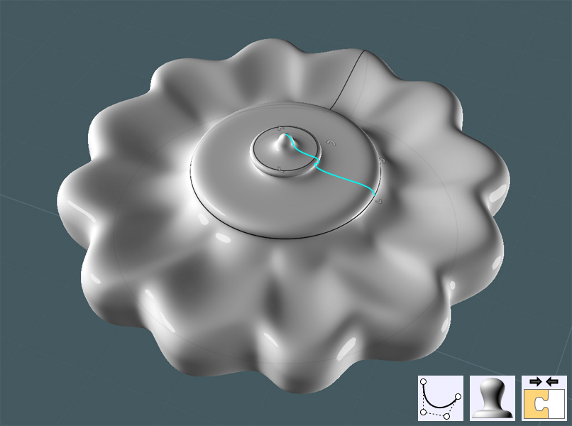
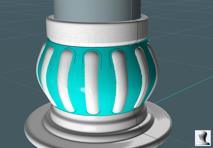
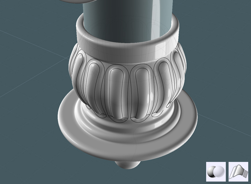
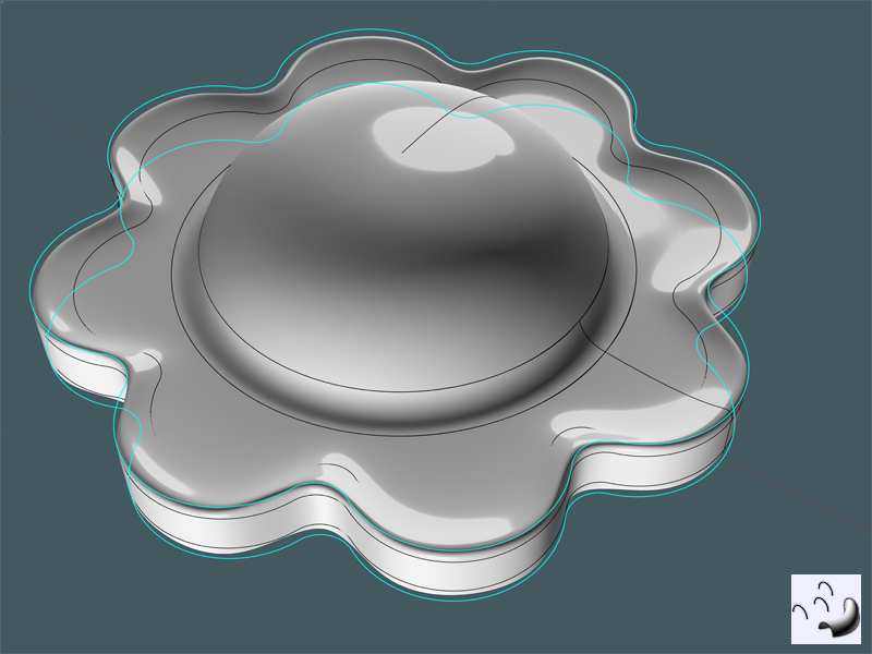
I made another floral looking knob by making profile rings and lofting them:


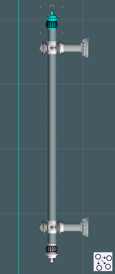
I position the bolts to their places:


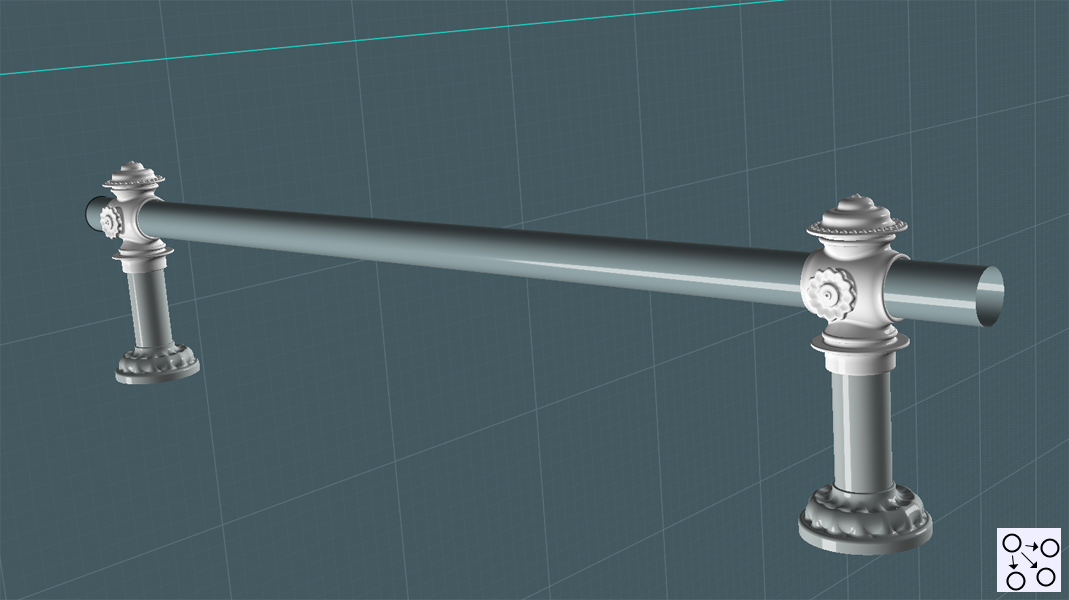
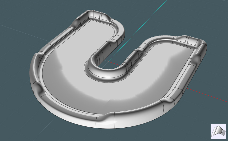
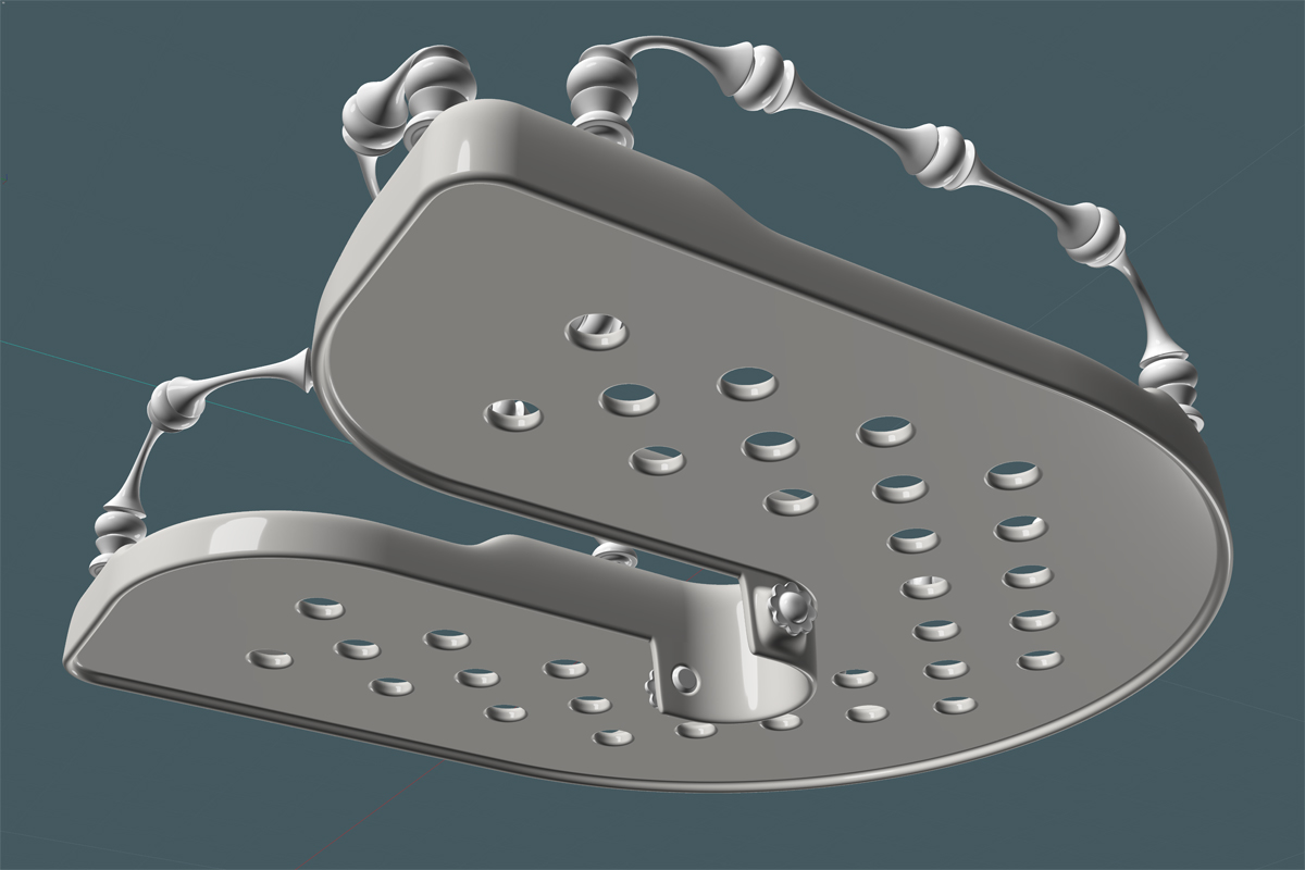
Here is the final Accessory Tray (from the top view)


(And from a below view)


Next: A mechanism to hold the shower head to the rig, and a connecting hose.
  Reply Reply More Options
Post Options
Reply as PM Reply as PM
Print Print
Mark as unread Mark as unread
Relationship Relationship
IP Logged

Previous
Next
 From:  ed (EDDYF)
4673.33 
"... Flowed to a Flow"

Clever. Flow Squared :)

Ed
  Reply Reply More Options
Post Options
Reply as PM Reply as PM
Print Print
Mark as unread Mark as unread
Relationship Relationship
IP Logged

Previous
Next
 From:  Stever_uk (STEVER)
4673.34 
Absolutely breathtaking

Nuff said
  Reply Reply More Options
Post Options
Reply as PM Reply as PM
Print Print
Mark as unread Mark as unread
Relationship Relationship
IP Logged

Previous
Next
 From:  Mauro (M-DYNAMICS)
4673.35 
  Reply Reply More Options
Post Options
Reply as PM Reply as PM
Print Print
Mark as unread Mark as unread
Relationship Relationship
IP Logged

Previous
Next
 From:  Rich_Art
4673.36 In reply to 4673.35 
Wow really nice model. Respect for your Moi handling....

Peace,
Rich_Art. ;-)

| C4DLounge.eu | Our Dutch/Belgium C4D forum. |
  Reply Reply More Options
Post Options
Reply as PM Reply as PM
Print Print
Mark as unread Mark as unread
Relationship Relationship
IP Logged

Previous
 From:  Mike K4ICY (MAJIKMIKE)
4673.37 
Thank you all very kindly guys!!! =-)

I hope there's a little bit in there to inspire your modeling.
  Reply Reply More Options
Post Options
Reply as PM Reply as PM
Print Print
Mark as unread Mark as unread
Relationship Relationship
IP Logged
 

Reply to All Reply to All


Show messages:  1-20  21-37