Majik Tutorial: Shower Head
 1-10  11-30  31-37

Previous
Next
 From:  Mike K4ICY (MAJIKMIKE)
4673.11 
Part Two: Hand-Held Shower Head Body

Here I will create a decorative body for the shower head.
BTW, this shower head is a hand-held model.

I've put a few days of thought into this. It needed to match the decor of my WIP bathroom scene.
I had some fancy designs in mind, but this is a fixture that is used every-day, and since it is hand-held, it needs to be sort of basic in overall shape.
Though, it can have a little pizazz put into it.

We need to draw profiles to make the main body shape with the Network command.

1) Freeform curves to make up a top and bottom profile line to run down the center (looking from the face)
Used the shower nozzle face and it's circle as a reference.


Notice how I made a lip shape to hold the nozzle head...


Now we need a symmetrical profile curve to represent the sides of the shower handle body.

2) Started in Right View and made the lip.


3) Then I continued drawing points for the curve in the Front/Back Views to carry the profile along the body.


4) I went into the Top View and shown the points of the curves, manipulating them to give it a nice curved shape from the top.


5) Mirror Command - to make the symmetrical copy of the side profile.
Note: By manipulating the points of the original shape, adjustments can be made to the mirror copy simultaneously by it's history state.


You can see the arrangement in 3D View...


To make a simple "Axial" Network surface, we now need at least two profile rings at each end of the profile rails created.
This one is simple:

6) Use the Ellipse by Diameter tool, select two opposite end points, then and adjacent point/ (As shown)
Because I used the original circle for the shower nozzle face as reference, the fourth side of the ellipse touched the remaining profile rail end.
However, you don't have to be dead-on for Network to work.


7) Next, I used the same ellipse tool at the other end of the rail set.
Because these were placed at an ad-hock angle, the bottom of the ellipse did not touch the curve-end. I suggest just moving the end point on that rail to touch the ellipse.


Nice...

8) Networked the combination of the rails and rings. All I needed was the two end rings in place and it saw the entire run.
Note: If you get strange results in the middle, using more rings throughout the course will give you more control.


Let's put some detail on that bad boy using the MoI V3's Flow tool!

9) Draw a simple reference plane.
Note: Show Points on the plane to make sure that the corner control points are in the corner and not a half mile down the street as shapes are made with the Planar command.


10) Now use the V3's new "Decoration Spray Tool" to add some neat elements...
C'mon silly... This is where you put your own toppings on it like a homemade pizza! ;-)
This tutorial cannot get into the detail of how I made those elements
- but if you like, here is the flourish shape: http://www.mediafire.com/file/upoj1nkvnnigxtx/flourish_shape_01.3dm


11) Used the Flow tool.

Here's a note on my placements: The seam on the Network mesh just happened to end up on one of the sides.
I divided the reference plane into two parts. One would be Flowed to the bottom and the other to the top as the objects were "rolled on".

The big technical aspect to consider when using the Flow tool is that Flow will match reference surface to target surface. And if the points arrangements on one surface is in a warped pattern that is not "grid-like" then the object will be warped to follow suit.
The points on the shower handle body were not straight, but had a strange warp to them. This forced all the objects on the reference plane to skew in accordance to the target surface's point-grid positions.

Remember when I said above that adding rings to your mesh would add control? That may have also "straightened" up much of the grid in the target surface as well.
But I played around with the arrangement a little until it looked good enough.

Working with the new Flow command is an art form within itself. It takes a little practice and understanding, but can become a powerful tool in NURBS modeling.

Step 1 - Select the objects to Flow.
Step 2 - Select the reference surface. When choosing this surface, keep in mind [where] on the surface you are selecting as you will need to match that orientation on the target surface.
Step 3 - Select the target surface. Pick a place on the target surface that will best match the orientation of the reference surface to your objects.
Step 4 - Preview... if the objects are on the wrong side, select the "Flip Normals" option. Done.


Kind of funky... BTW, don't expect to Boolean anything with the main surface the objects are flowed too. The underlying points are too convoluted.
It's best to use a copy of the reference surface to make a "new" surface with the object already attached.


Kind of neat...
Objects are very warped, but it will work for this tutorial.


I need to finish out the bottom part of the shower handle by adding some kind of end where the water supply hose will attach.
There are two things about the arrangement here that makes it a slight challenge: One, the circle on the end is not perfectly flat or "circle". Two, it's oriented at an angle.

I need to make a revolved shape, but regular revolve might not match the imperfect circular end.
I could use a sweep of a profile along the end circle as a rail, but I may get a pinched result at the end as sweep was not meant for perfect revolves.

The easiest thing to do is Revolve by Rail.

12) To get an axis reference from the circle, I'll make this extrusion first, and then use it's ends to find the center with some construction points.


13) Delete the extrusion object and draw a revolve profile shape.


14) Revolve by Rail to make the object.


Now matter what you do, Revolve by rail will only make a flat bottom shape that will not match to the imperfect rail shape it followed...
A Sweep would have done this, and the result would have been nice, if I would have thought to put a small circle at the other end for sweep to follow... ;-p

None the less... I moved the revolved shape apart from the end of the network mesh and
15) Blended the two edges together.


Here is a shot of the final hand-held portion of the shower head assembly.
This will look nice when rendered in antique brass!


Here are a few more views.


---In Part Three: The remaining water hose and adjustable wall mounting parts will be created. And a nice render to follow.
  Reply Reply More Options
Post Options
Reply as PM Reply as PM
Print Print
Mark as unread Mark as unread
Relationship Relationship
IP Logged

Previous
Next
 From:  Rich_Art
4673.12 In reply to 4673.11 
Thanks again for this great workflow "tutorial" :-)
The showerhead looks really great...

Peace,
Rich_Art. ;-)

| C4DLounge.eu | Our Dutch/Belgium C4D forum. Cinema4D R13 Studio + VrayForC4D + UVLayout Pro + 3DCoat
  Reply Reply More Options
Post Options
Reply as PM Reply as PM
Print Print
Mark as unread Mark as unread
Relationship Relationship
IP Logged

Previous
Next
 From:  Frenchy Pilou (PILOU)
4673.13 
Art deco ! :)
---
Pilou
Is beautiful that please without concept!
My Gallery
  Reply Reply More Options
Post Options
Reply as PM Reply as PM
Print Print
Mark as unread Mark as unread
Relationship Relationship
IP Logged

Previous
Next
 From:  Mike K4ICY (MAJIKMIKE)
4673.14 
Part Three: Wall Mounting Parts - Building the Escutcheon Plate

First I'll start with the escutcheon (Gesundheit!). This is the decorative plate that hides the screws and cuts in the tiles on the wall.
I'll be using the one I created for the decorative toilet handle so that it will match, but I'll show one being made here to be a persistent in the progression of this project.

The first one I made was by using the Loft command with many shaped rings. It failed and made an ugly shape. But I "made lemons from lemonade" and used some of the pieces to make something that looked unique.


When making this escutcheon, start off with actually using the inner and outer circle diameter that will be needed.

In this case, I'd like to use a 1.5" OD pipe.

Tell MoI to make a circle with your inner dimension:


If done before clicking the diameter point with the circle tool - simply type in the diameter.
If needed to be done after making the circle - click on the size description at the top of the side-bar and a dialog will emerge.

Make the outer circle:


I used a diameter of 3.5"

Raise the smaller inner circle up to any height:


Draw a nice side profile shape in a side view with one of the curve tools:


Go to the Top View and rotate it off a little to the side. This will be the edge of one of the detail shapes:


Mirror this curve on center:


Show Points on the original curve, Show Points and manipulate the points to make an interesting shape:
Note that the mirror curve will mimic the points manipulation as part of it's immediate history.


Draw a 3-Point Arc off of the end points at the bottom of the two curves. It should bulge out some.


Make an Arc at the top that matches the curvature of the top circle exactly. Or trim the top circle to get an exact match:
You can make this surface a couple of ways - A Sweep will work. I used a Network because it made the area at the mid-section bow in instead of out.


Circular Array the surface:
Choose enough copies so that there is around the same amount of distance in-between the surfaces.
Choose the center of the circles for the pivot.


Blend a surface between adjacent edges of tho of the detail surfaces:


Since each of the surfaces should be exactly the same - simply Circular Array copy the Blend surface:


All surfaces should Join to one surface. If a part does not, delete it and re-blend that part.


Extrude the bottom ring: Size it a little larger if need be. You only need a planar surface on top of the new cylinder.


Fillet the top edge to make a nice round-over:


I made two lines snapped from the center point and ending snapped to the inner circle created by the fillet.
They should end up close to where the intersecting edges of each smaller body section project to the inner circle.
- You'll see below.


Circular Array copy each set of lines - then run the Trim command with all of the lines and the inner circle:
The lines were put there to cut the inner circle into smaller section curves that will used to Blended to the above surface sections.


Here, I blended the upper body surface section edges to the cut section edges of the side lip of the filleted round-over.
"Drill" select the smaller curve segments on the inner circle and the edge segment curves on each above surface.
Do this all the way around. If you have problems with the sides of the new Blend surface matching, try using Trim to cut the segments into smaller pieces, then try Blend again.


...I did just that when the bottom portion was really two separate segments because of a seam line.
(Worry not - Michael has a better Blend tool in his list where Blend will work across seams and broken separate lines. ;-) )


Everything should Join together into one contiguous surface.


Make the lip for the inner opening to the escutcheon.
Use the Freeform curve tool to make a profile.

I snapped the new curve to the TANgent of the underlying surface's edge.
How did I find a way to snap to the tangent of a surface?
I drew a line along center-X and projected that line to the top of the surface area below, so that when I looked through the Front View port, there was a curve with an endpoint to snap to...


Use Sweep or Revolve to make the lip:


Surprisingly when I went to Join the bottom surface sections to the top lip sweep - everything matched and join into one smooth surface!
It was not this easy when I made the first one. I had to blend sections, cut and everything else to join the matching sections.
This one worked because I made sure the swept surface above was exactly tangent and matching to the underlying surface edge.


Not just revolved or lofted shape, this has some detail. You can add other ridges, floral or leafed patterns, jewels or dots to it as well.

---Next Part: The framework that holds the shower head and other accessories...
  Reply Reply More Options
Post Options
Reply as PM Reply as PM
Print Print
Mark as unread Mark as unread
Relationship Relationship
IP Logged

Previous
Next
 From:  Frenchy Pilou (PILOU)
4673.15 
Wonderful serial !
---
Pilou
Is beautiful that please without concept!
My Gallery
  Reply Reply More Options
Post Options
Reply as PM Reply as PM
Print Print
Mark as unread Mark as unread
Relationship Relationship
IP Logged

Previous
Next
 From:  Mike K4ICY (MAJIKMIKE)
4673.16 In reply to 4673.15 
It's like watching a foreign soap-opera...

1) The suspense!
2) It draws on forever.
3) You don't know what they're saying for the most part.
4) Nice Shapes and attractive curves. And the shower scenes are worth the wait. ;-) hootchie mama.

(NURBS curves and the rendered shower scene, of course)
  Reply Reply More Options
Post Options
Reply as PM Reply as PM
Print Print
Mark as unread Mark as unread
Relationship Relationship
IP Logged

Previous
Next
 From:  ed (EDDYF)
4673.17 
Yikes! =:0

That's some intense modeling Magic.

That's gonna be a bathroom even Donald Trump would be jealous of.

Ed
  Reply Reply More Options
Post Options
Reply as PM Reply as PM
Print Print
Mark as unread Mark as unread
Relationship Relationship
IP Logged

Previous
Next
 From:  Mike K4ICY (MAJIKMIKE)
4673.18 In reply to 4673.17 
Thanks,

I'll have to render everything in polished 24 karat chrome-gold for Donald then.
  Reply Reply More Options
Post Options
Reply as PM Reply as PM
Print Print
Mark as unread Mark as unread
Relationship Relationship
IP Logged

Previous
Next
 From:  SteveMacc (STEVEH)
4673.19 
Not exactly Scandinavian styling, then. Don't think you'll get a job at Ikea, Mike.

Excellent modelling techniques, by the way.
  Reply Reply More Options
Post Options
Reply as PM Reply as PM
Print Print
Mark as unread Mark as unread
Relationship Relationship
IP Logged

Previous
Next
 From:  Mike K4ICY (MAJIKMIKE)
4673.20 In reply to 4673.19 
But then whatz am I gonna do wiz all that goooooold?!

Oh vell... I might of had a very unfortunate schmelting accident.


I can not understand Scandinavian styling because I have a Dusch accent, cantz you tell? Insteadz, I am from Holland! Isn't that viert?


But yesh! My modeling techniques are getting very toight, yesh, toight like a toiger, yesh yesh yesh!


...ahh... it's late. ;-)
  Reply Reply More Options
Post Options
Reply as PM Reply as PM
Print Print
Mark as unread Mark as unread
Relationship Relationship
IP Logged

Previous
Next
 From:  Rich_Art
4673.21 In reply to 4673.20 
[quote] I am from Holland! [/quote]

Really?? That is cool. :-)

Peace,
Rich_Art. ;-)

| C4DLounge.eu | Our Dutch/Belgium C4D forum. Cinema4D R13 Studio + VrayForC4D + UVLayout Pro + 3DCoat
  Reply Reply More Options
Post Options
Reply as PM Reply as PM
Print Print
Mark as unread Mark as unread
Relationship Relationship
IP Logged

Previous
Next
 From:  Mike K4ICY (MAJIKMIKE)
4673.22 In reply to 4673.21 
lol... sorry, movie quote. No, not really. ;-)

Some more recent forefathers were.
  Reply Reply More Options
Post Options
Reply as PM Reply as PM
Print Print
Mark as unread Mark as unread
Relationship Relationship
IP Logged

Previous
Next
 From:  Rich_Art
4673.23 In reply to 4673.22 
ah haha ok. :-) Dus dit kun jij dan niet lezen? LoL

Peace,
Rich_Art. ;-)

| C4DLounge.eu | Our Dutch/Belgium C4D forum. Cinema4D R13 Studio + VrayForC4D + UVLayout Pro + 3DCoat
  Reply Reply More Options
Post Options
Reply as PM Reply as PM
Print Print
Mark as unread Mark as unread
Relationship Relationship
IP Logged

Previous
Next
 From:  Mike K4ICY (MAJIKMIKE)
4673.24 In reply to 4673.23 
Met een vertaler, ik kan! ;-)
  Reply Reply More Options
Post Options
Reply as PM Reply as PM
Print Print
Mark as unread Mark as unread
Relationship Relationship
IP Logged

Previous
Next
 From:  Rich_Art
4673.25 In reply to 4673.24 
hahahahahaha cool...
sorry back on topic. ;-))

Peace,
Rich_Art. :-)

| C4DLounge.eu | Our Dutch/Belgium C4D forum. Cinema4D R13 Studio + VrayForC4D + UVLayout Pro + 3DCoat
  Reply Reply More Options
Post Options
Reply as PM Reply as PM
Print Print
Mark as unread Mark as unread
Relationship Relationship
IP Logged

Previous
Next
 From:  Mike K4ICY (MAJIKMIKE)
4673.26 
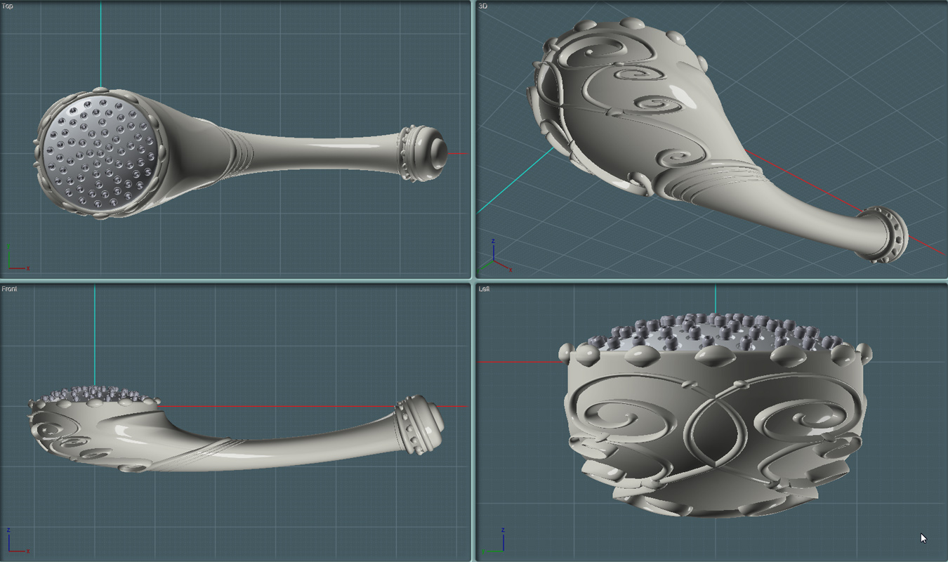
Part Four: The Adjustable Shower Bar


This is the assembly rigging that holds the shower head handle and allows it to adjusted for use.
You can also attach other items, such as an adjustable shampoo and soap tray.

It's very basic. Just a bar and two braces to hold it to the wall.
But most of the work will be invested in the fru-fru rococo-ness of the assembly's superficial design. ;-)


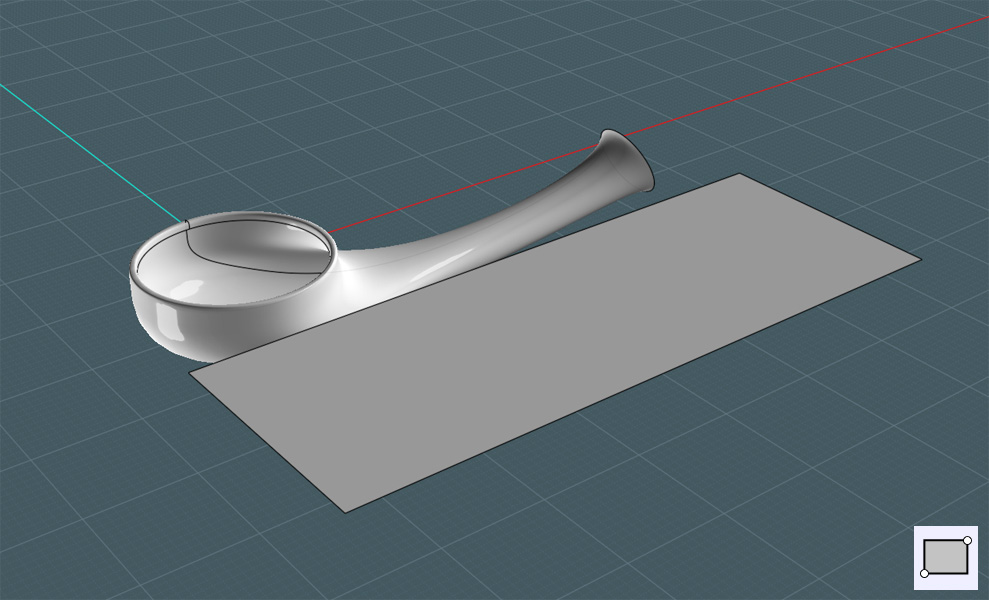
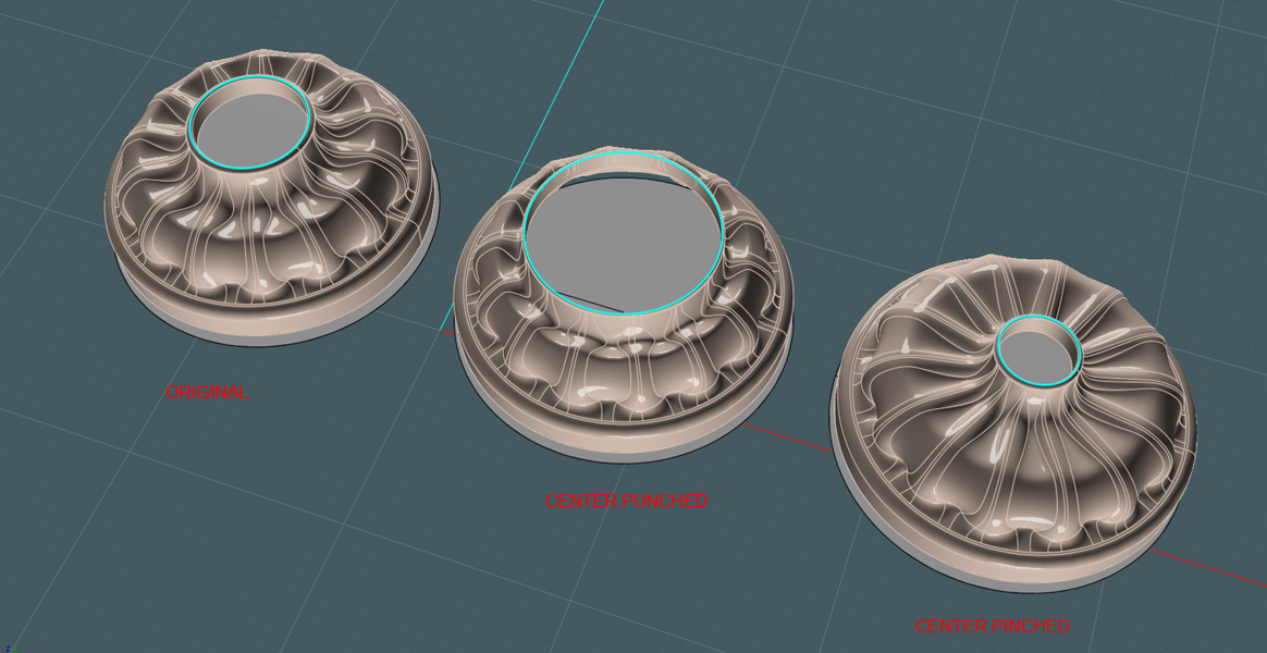
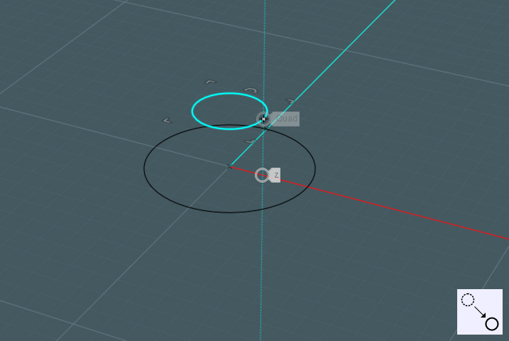
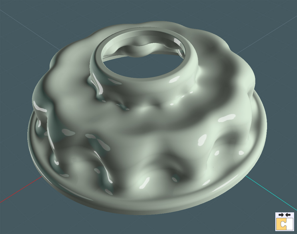
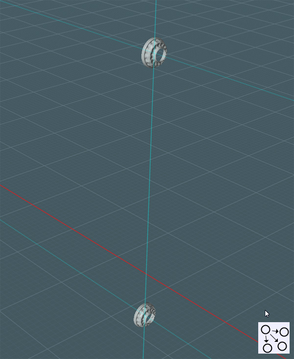
First we take the escutcheon cover that was made earlier and place two of them as they would be on the shower wall above the tub or shower floor.


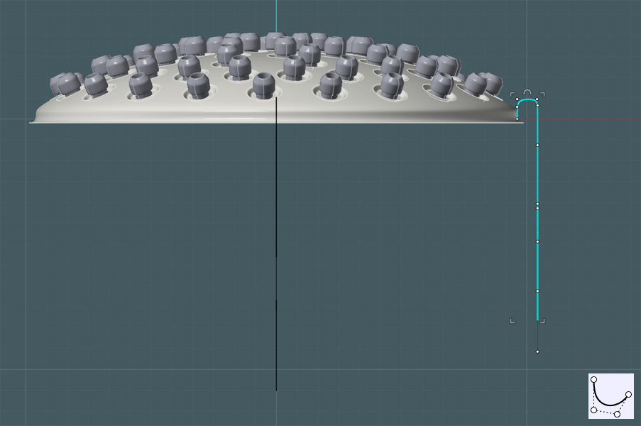
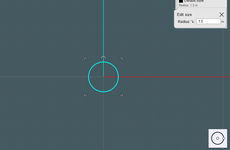
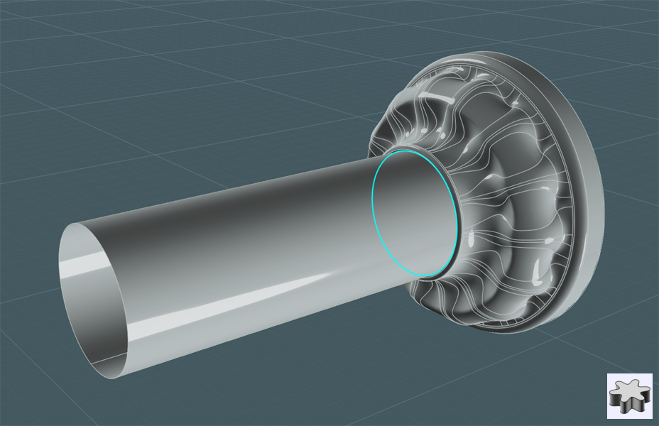
The center hole in the cover was made to be 1.5" d. To make an instant pipe, simply Extrude one of the center circle shapes.
This will complete the brace.


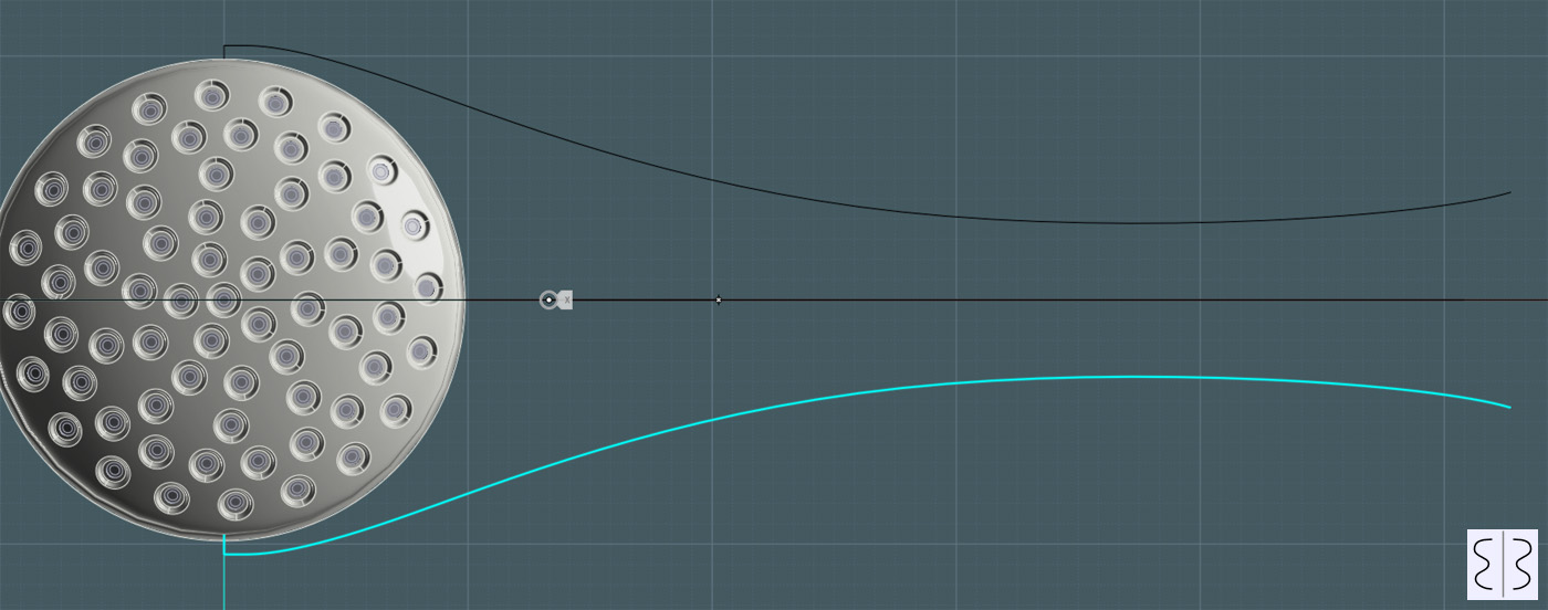
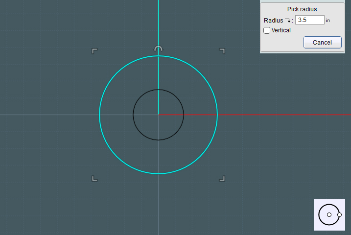
Use construction lines to infer the pipe sizing to create a circle for the vertical bar, (or copy the extruded object).


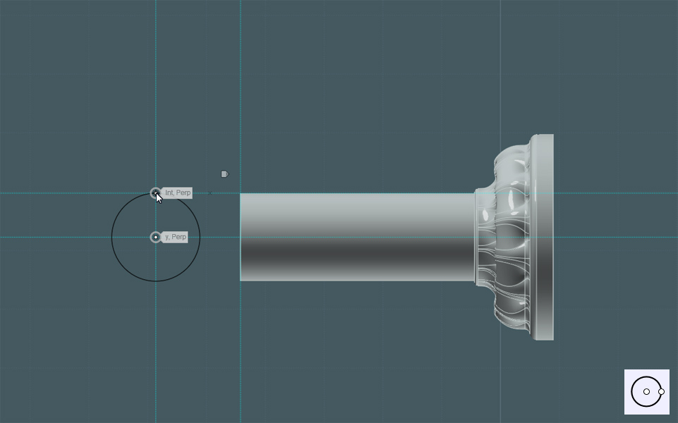
And Extrude the circle. Any length will do.


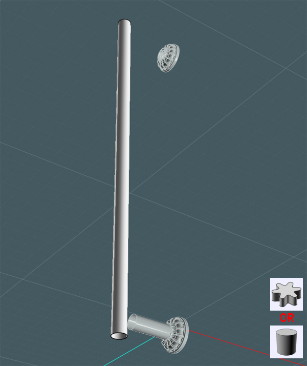
Later, I'll be replacing this bar with one having a little more detail.


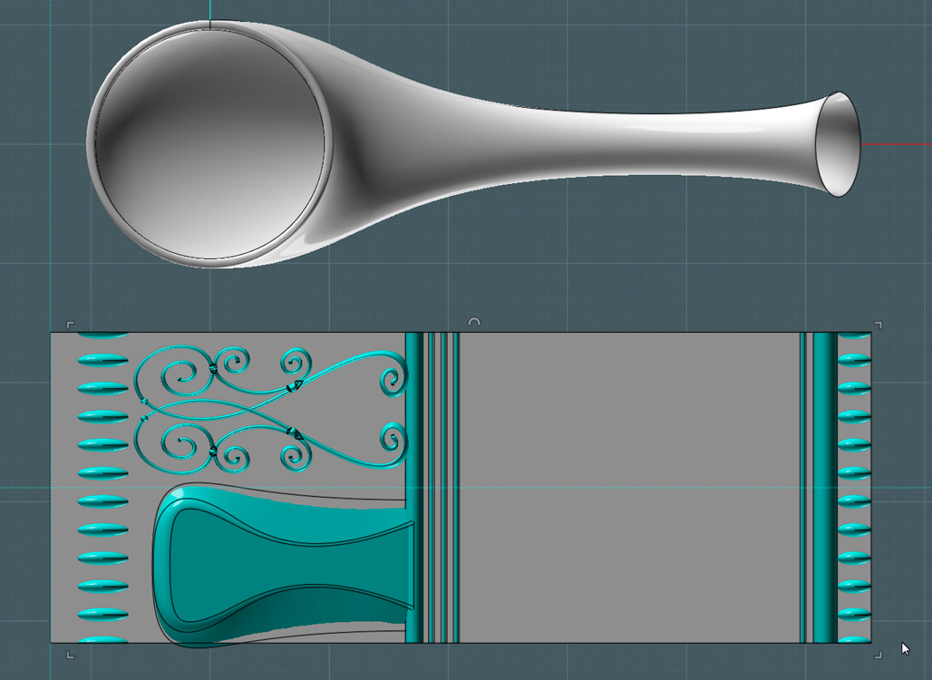
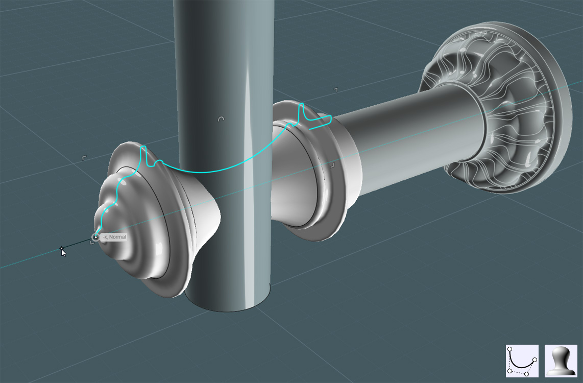
Here is where you can have a little fun:
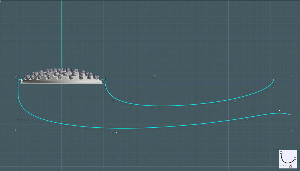
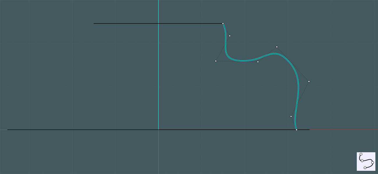
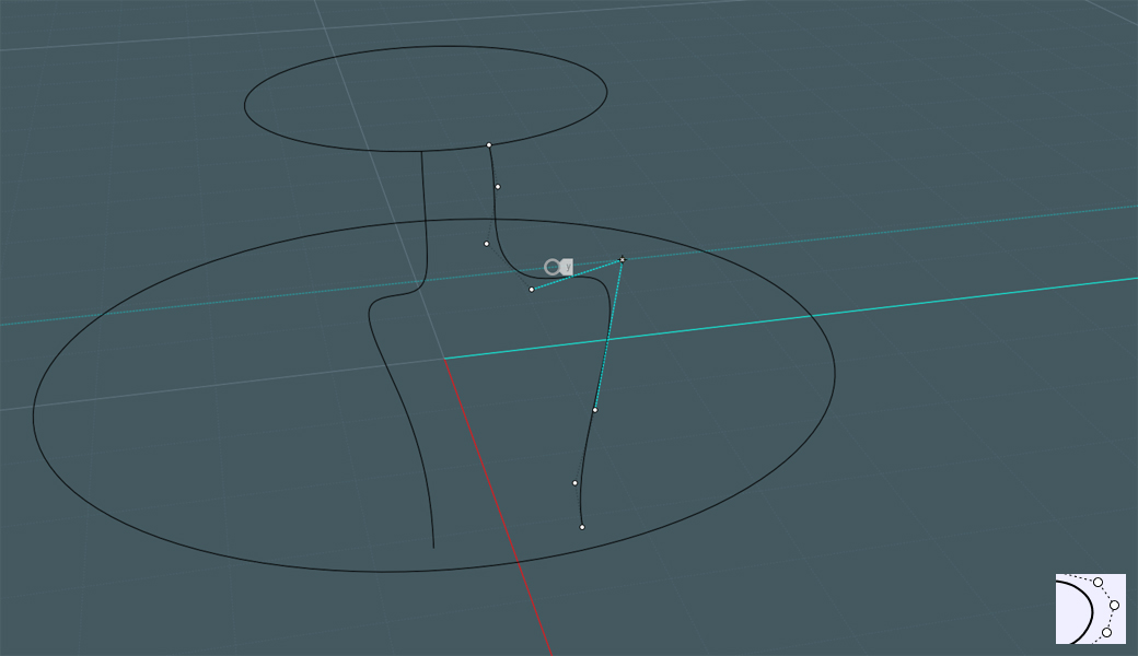
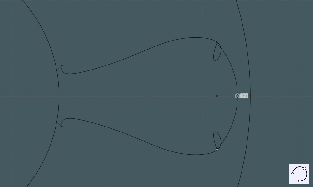
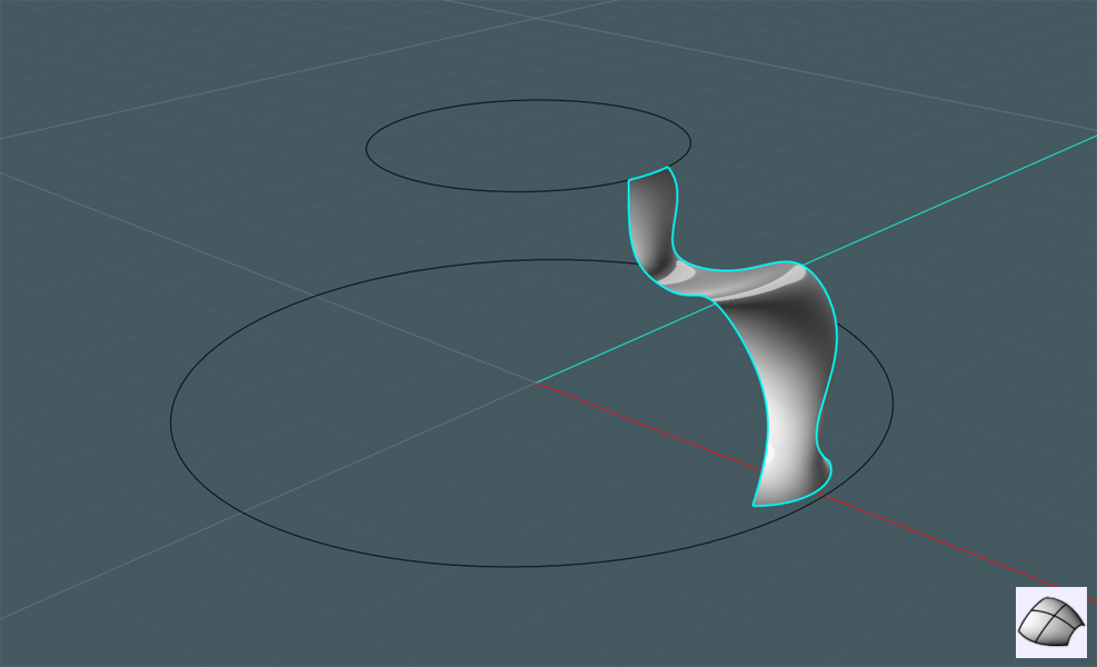
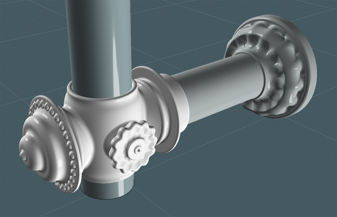
Create a profile with your curve and line tools. Then Revolve the shape to make an interesting object to act as the bar and brace union section.


Why not decorate it?
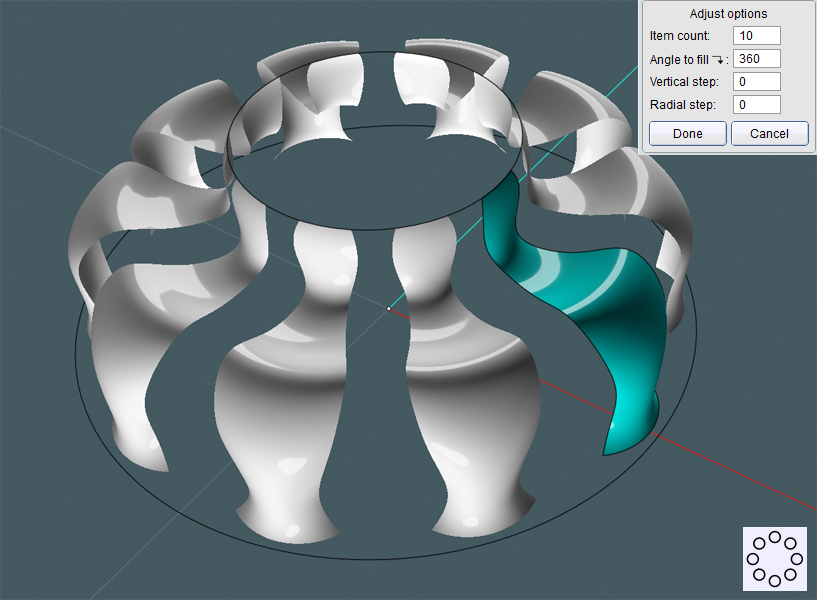
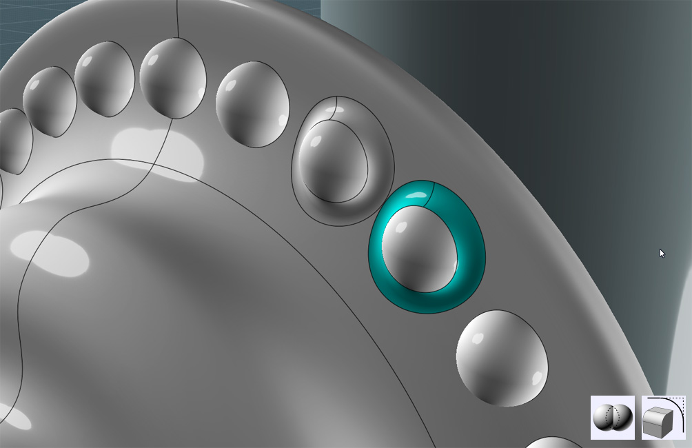
I created a small Sphere in one of the circular areas and sunk it half-way into the object. Then I Circular-Arrayed copies of it.


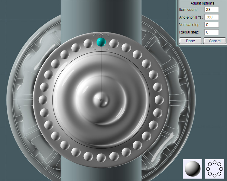
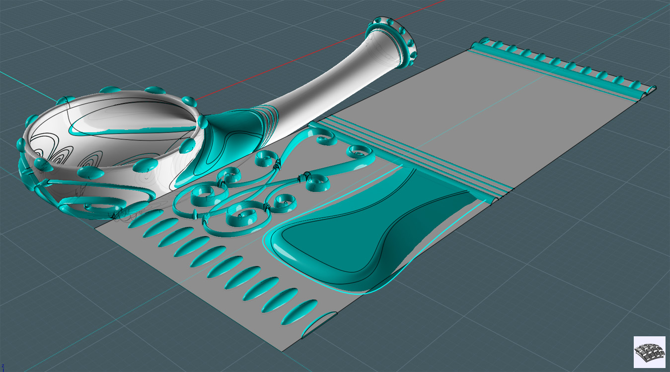
And to give the decoration a real molded/pressed look I Boolean Unioned the spheres and Filleted the resultant mating edges.


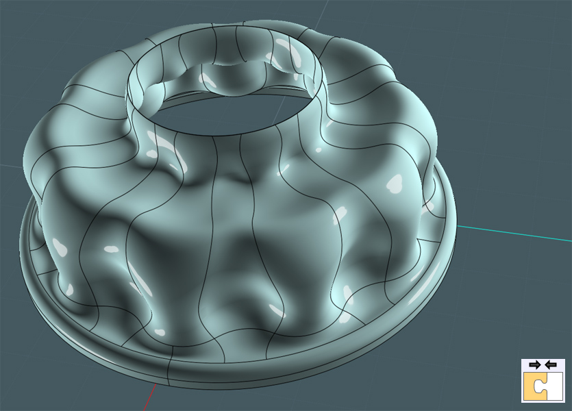
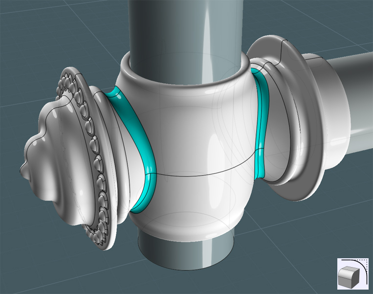
I created a profile shape and Revolved it around the vertical bar.
Inside of this piece would be a nylon friction sleeve and the housing for the friction lock.


Union the two revolved objects together.


Simply Fillet the mating edges to make a smoothed transition.


Okay... There's nothing simple about this. This is my second attempt and the Fillets did not want to take until I re-Revolved a new center shape. You may also try Difference cutting the shapes into sections and Blending their edges.


This bar is adjustable. So there has to be a frictioned tension adjustment knob on the side.
Yes, there are braces that would essentially be fastened to the wall in fixed positions, but there is still a need for lee-way with attaching extras.
And this model illustrates the principal of the design.

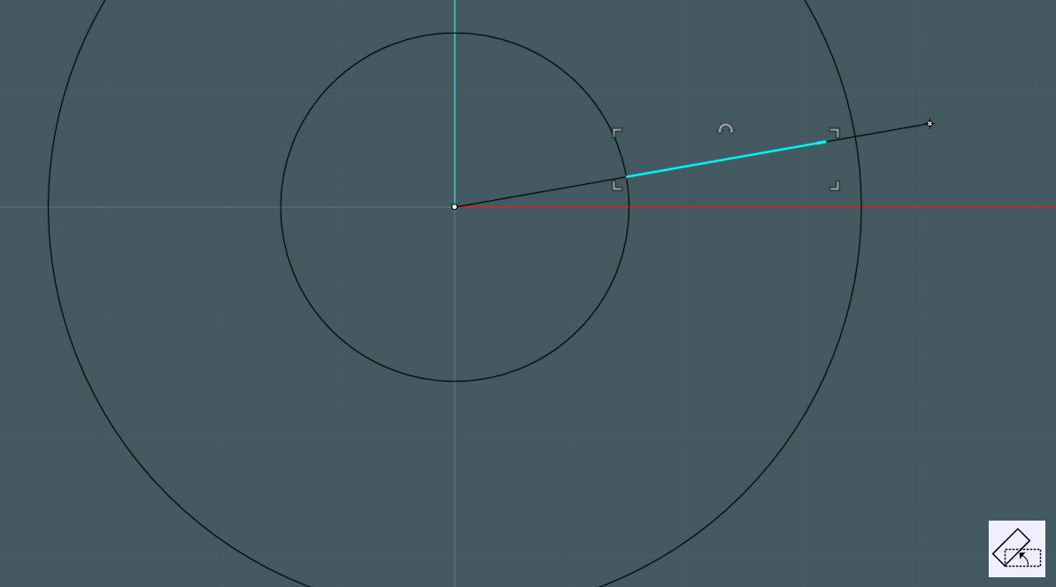
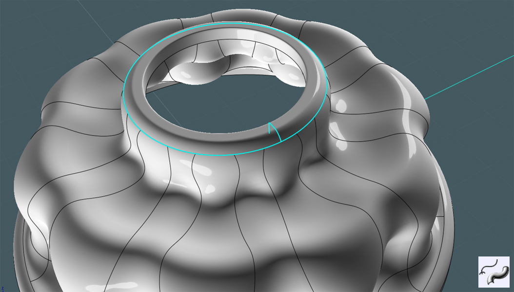
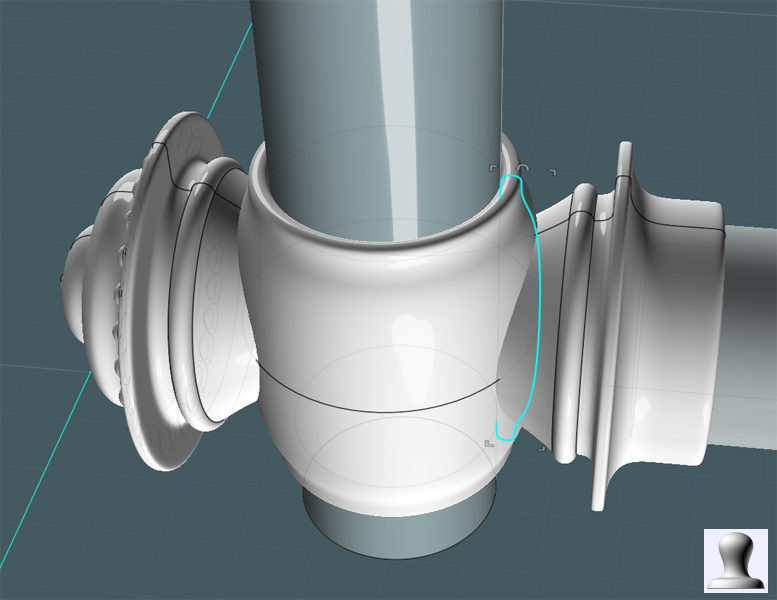
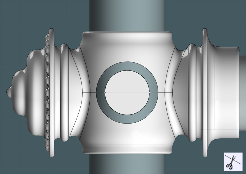
Create a couple of circles from the center of the vertical bar.


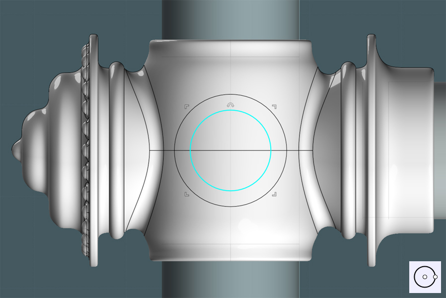
Make a Projection of the larger circle to the side of the shape.


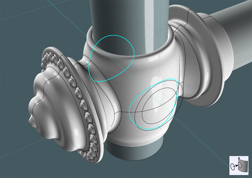
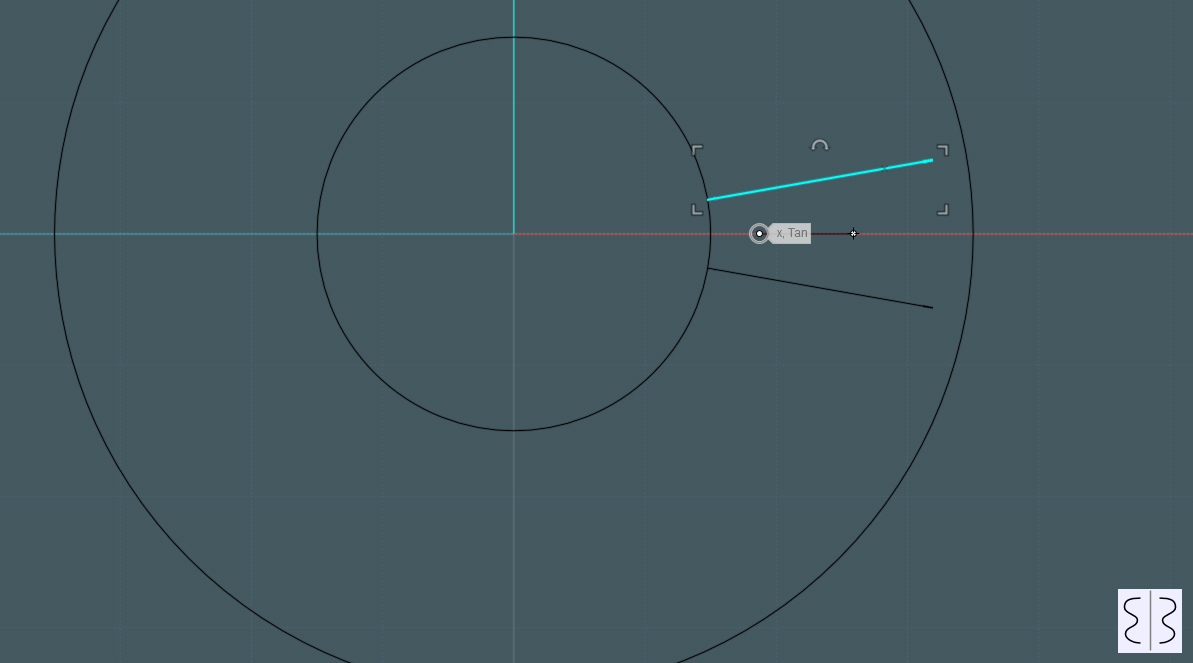
I trimmed a larger circle out of the main object's side and made the inner circle Planar.
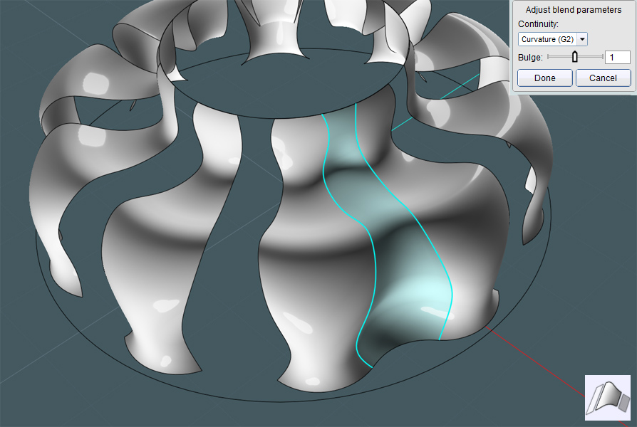
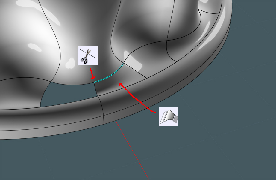
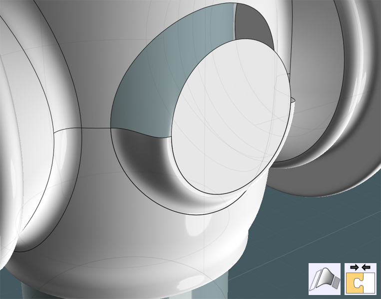
Yes, I want to Blend the surface edge of the hole in the side to the edge of the planar circle.
Because the main object has a seam line running through the middle of the hole, I Trimmed the edge curves with "Add-Points" to create two matching edge sections.


I Blended the edges and then joined all associated surfaces.
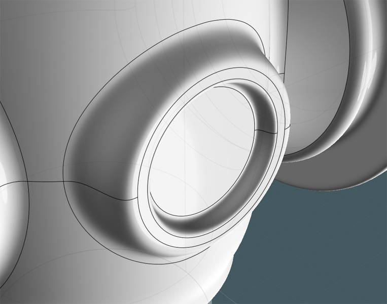
As you can see, there is now a smoothly made protrusion from the main object's side.


I did a similar procedure to create a custom inset.


Here, I'll make a knob to go on the side. It will have a floral look to it.
So, Let's create a small circle and Circular-Array it around a center point making sure that the circles overlap.


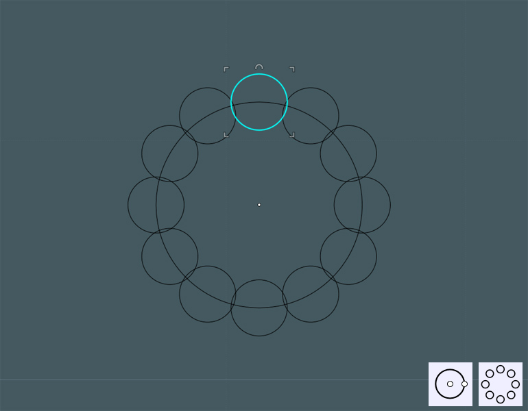
Boolean Union the circles and delete the remaining inside shape.

Fillet will smooth out the sharp creases...


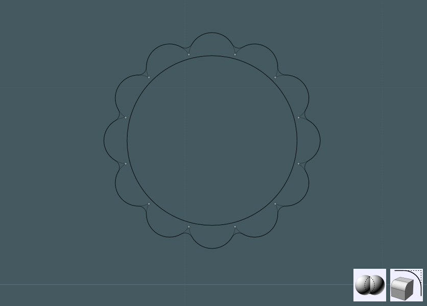
Now we will use MoI V3-Beta's new "Majik Cloud and Rainbow" maker... You do know about it, right? ;-)

Just kidding! A little Photoshop to show effect.
Here, the floral shape was copied and arranged - and a few circles were also added.

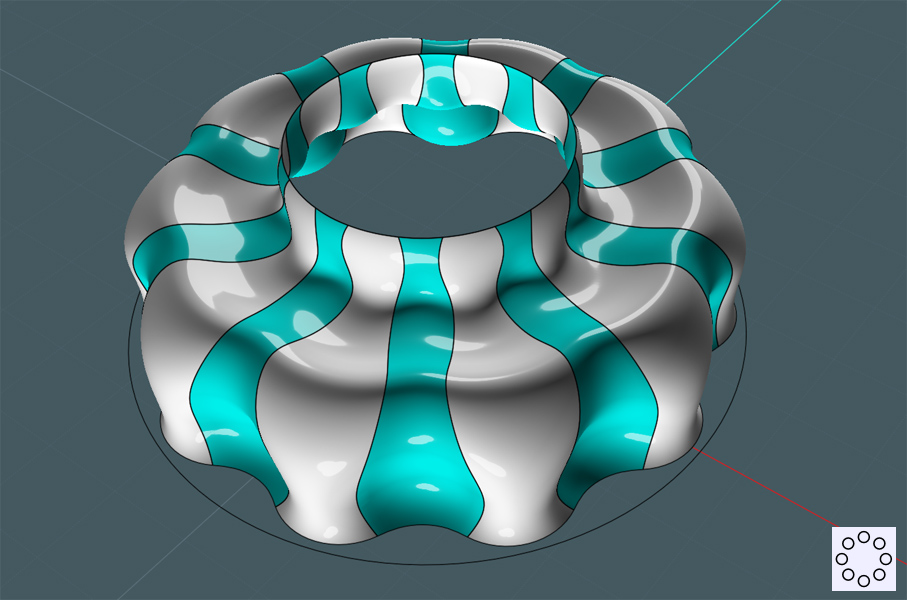
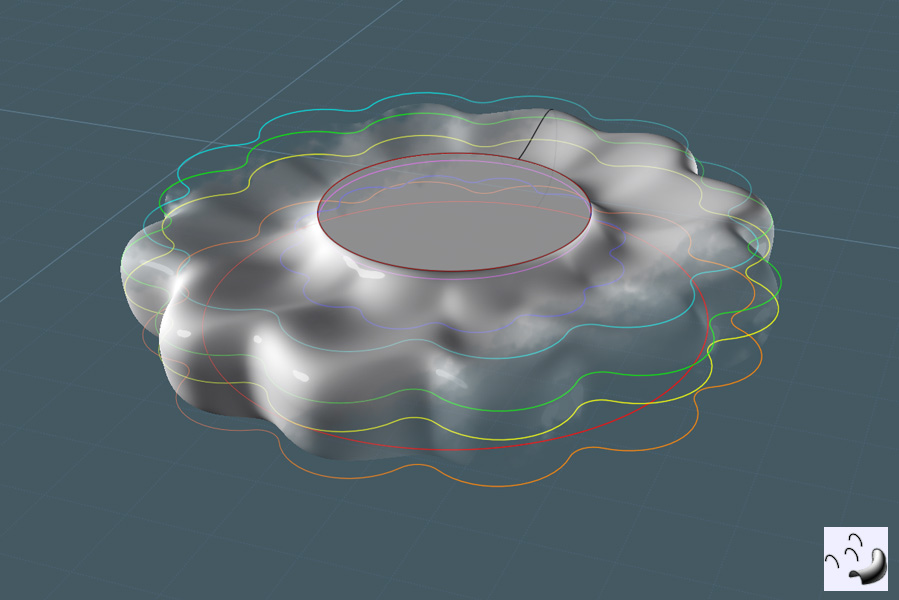
The image below illustrates that (following the color transition:) a Loft was then performed with profile rings that were selected in the order by which the surface was created.
In this example, from top to bottom. The Loft command was set to the "Loose" setting, and a neat floral shape was produced.


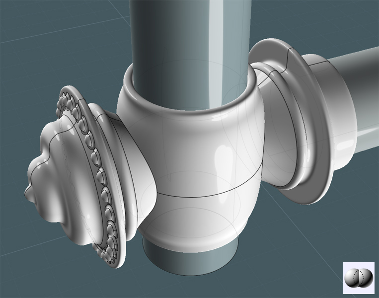
A Revolved profile completed the tension knob object. An extruded circle was made from the bottom to create a bolt.
All surfaces were Joined together.


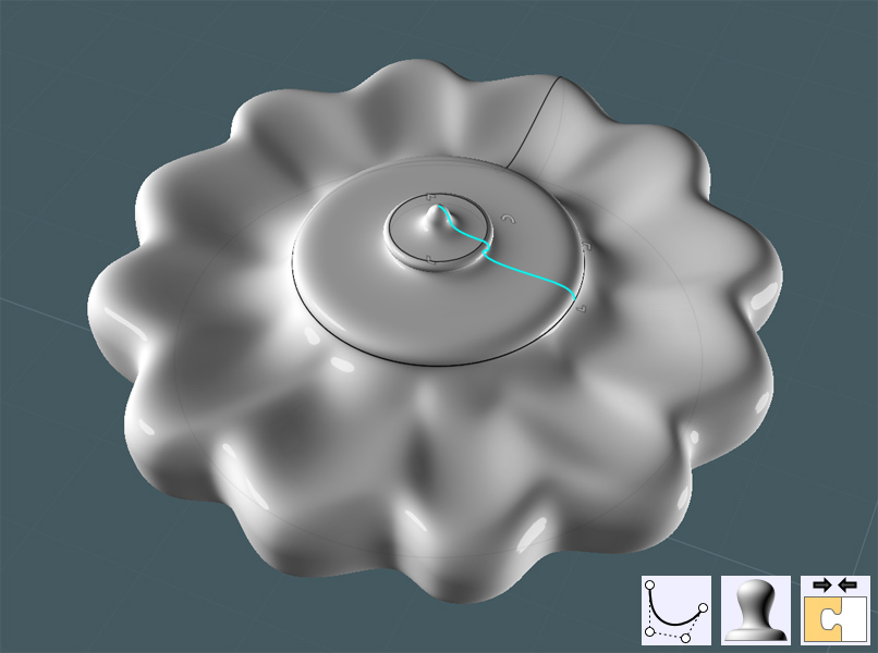
The tension knob was rotated, and moved to alignment with the main object.


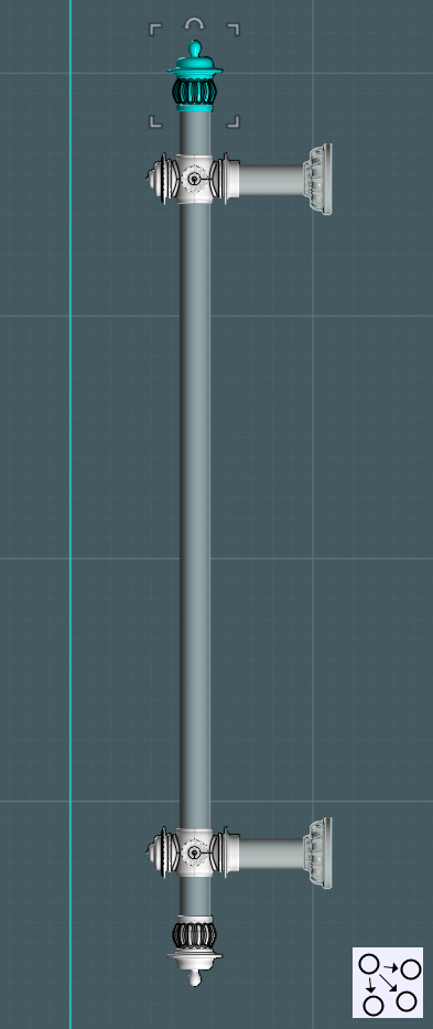
A copy of the entire brace and union set was copied to the upper part of the vertical bar.


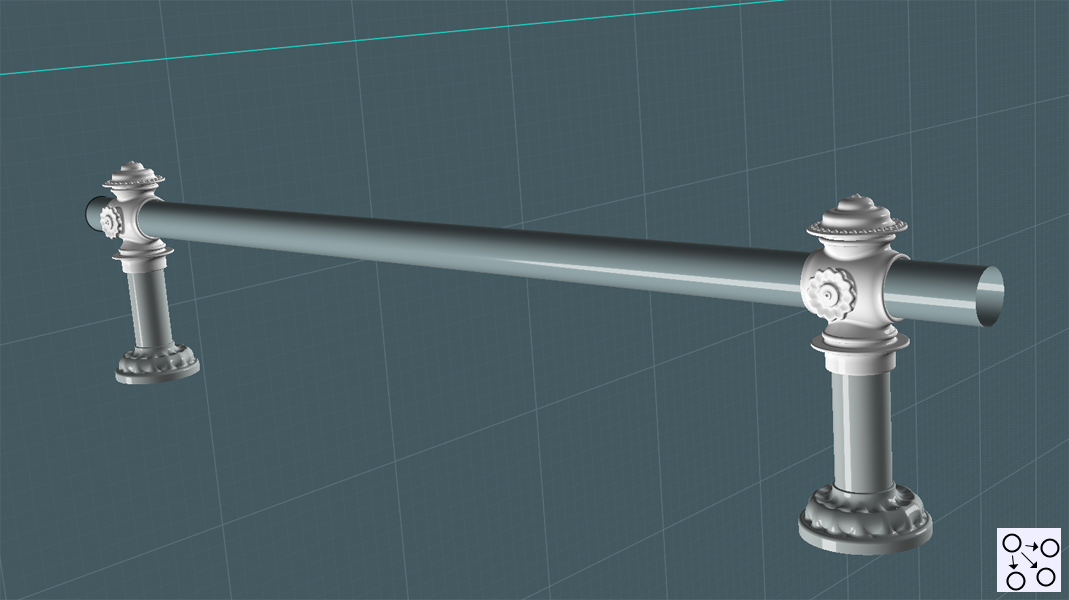
As you can see - this model can later be recycled to make decorative walk-way rails. Yes mates - Queuing in style!

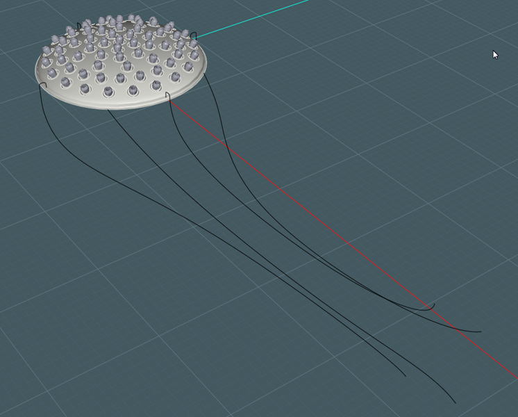
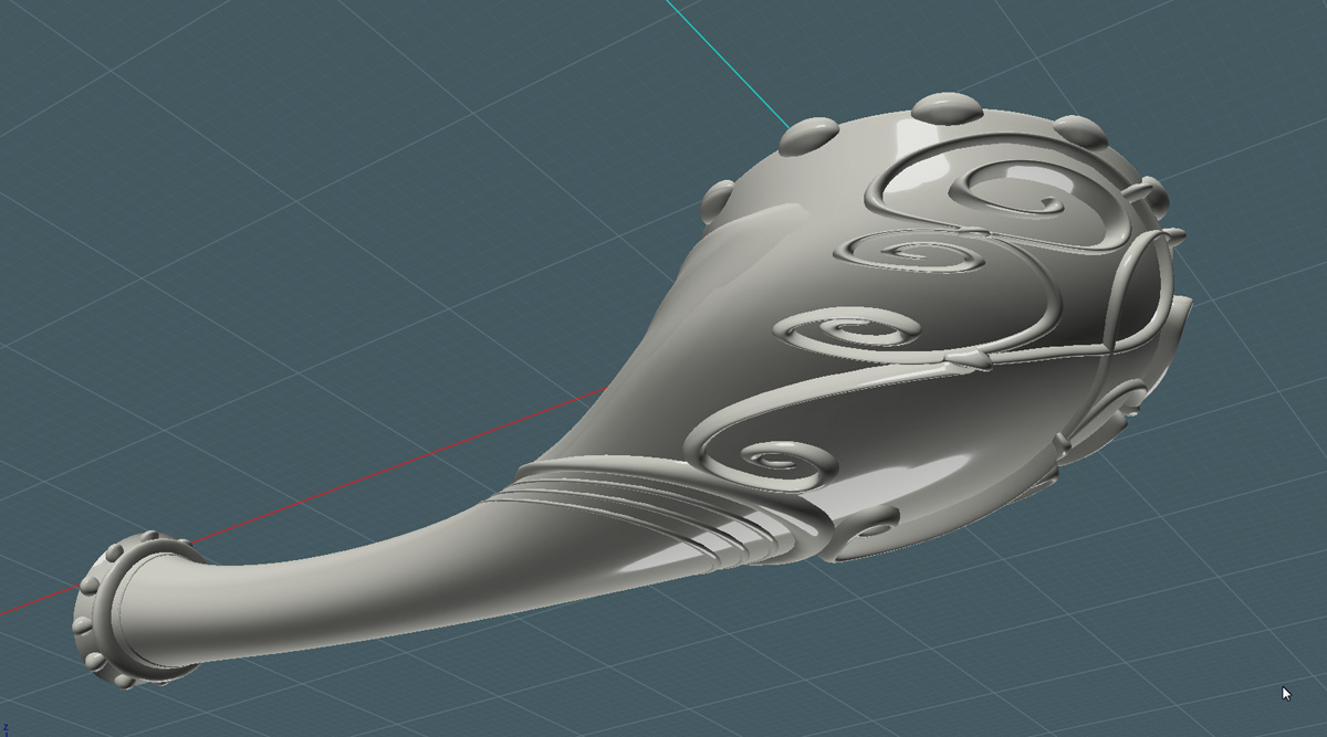
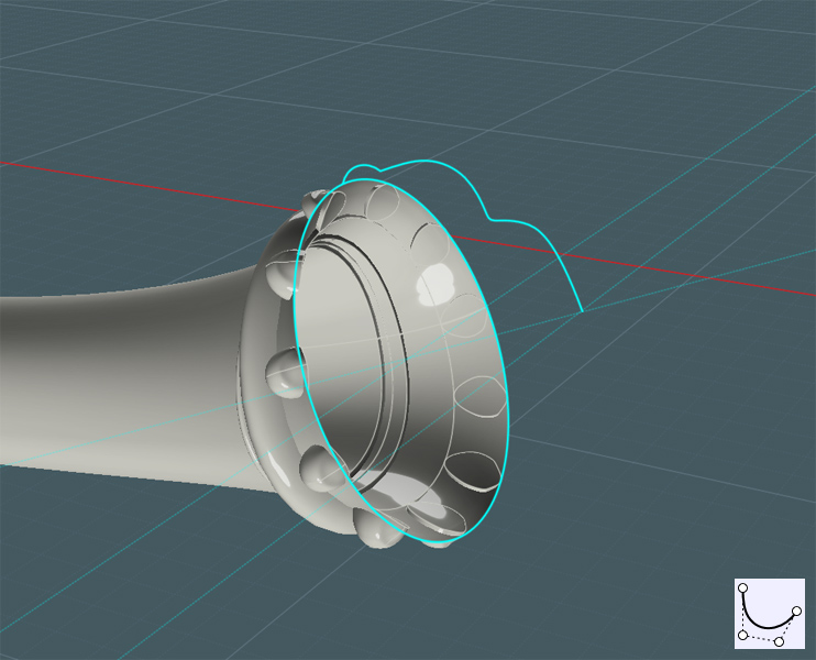
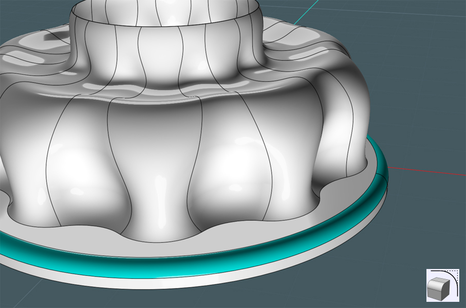
Now to cap the bar ends:

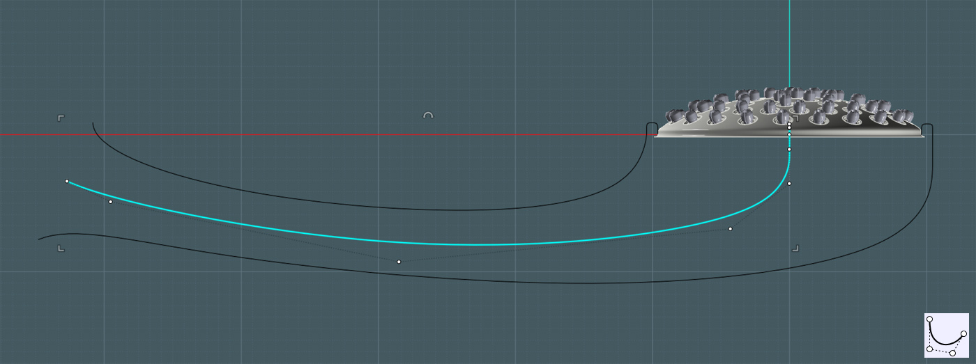
A profile curve is made and Revolved using the center snap point of the vertical bar's bottom circle for the axis.


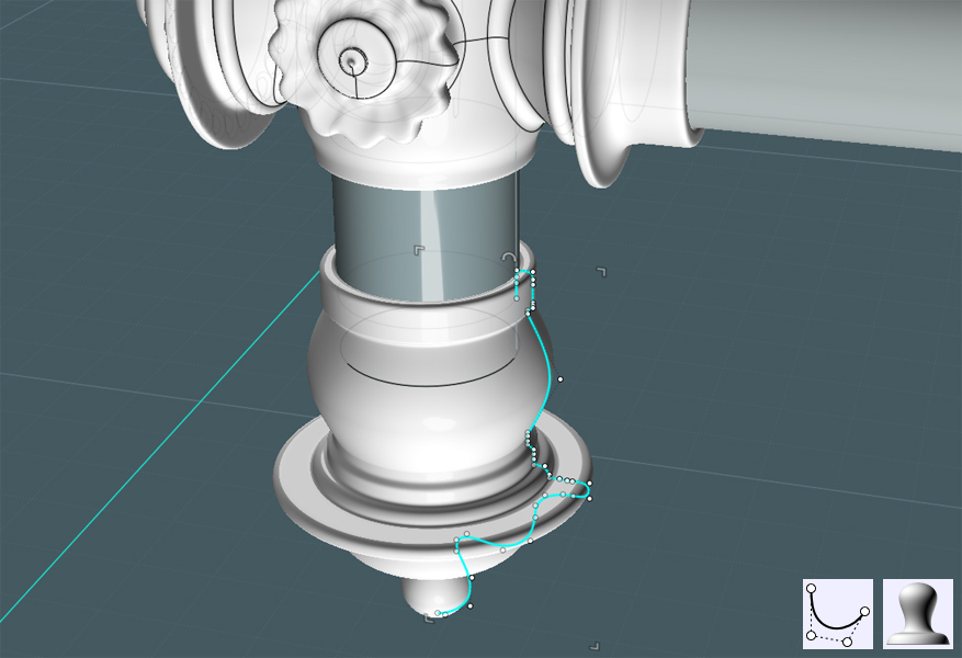
I made a broad curved space to add detail like fluting.
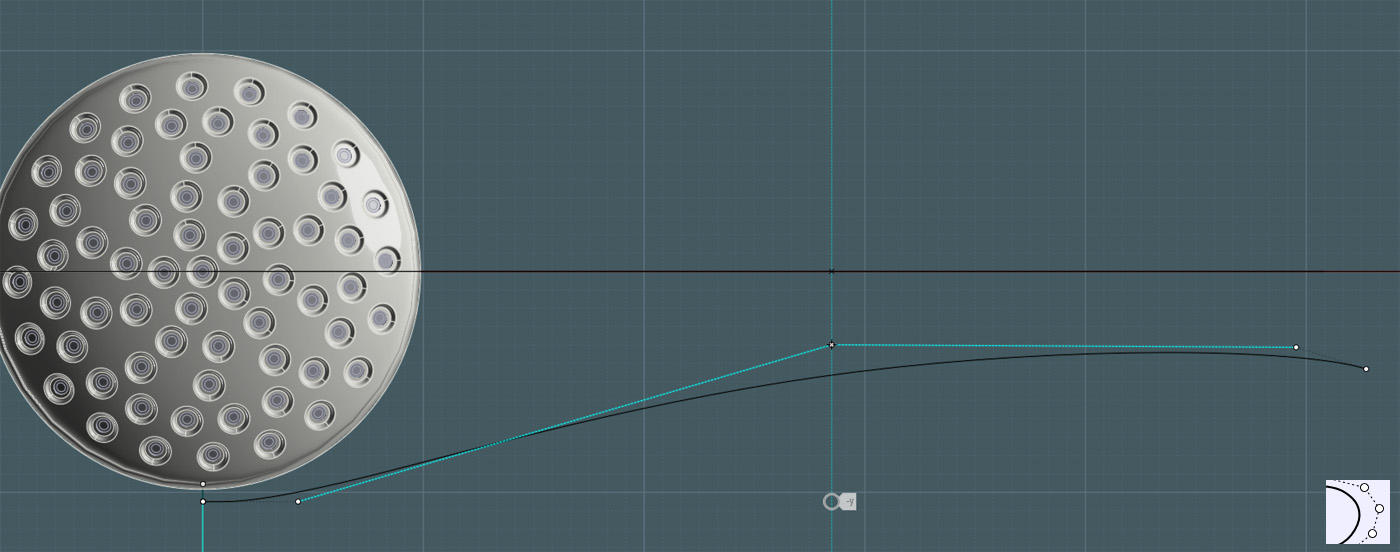
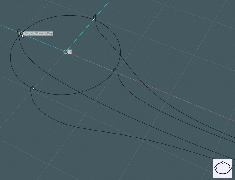
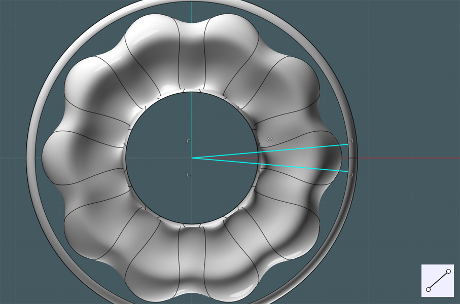
I made a Freeform curve to mimic the edge of the revolved surface.


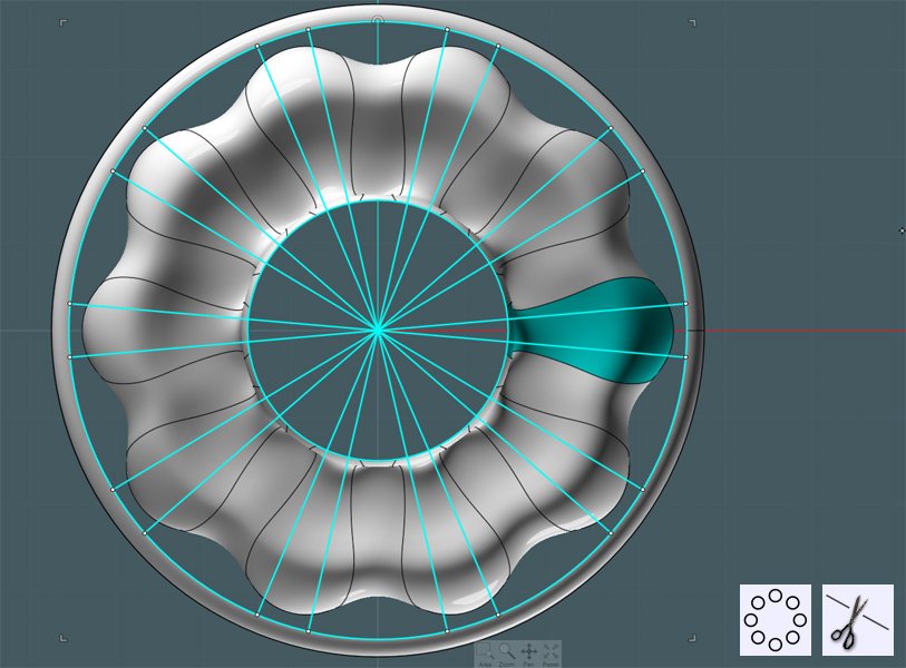
I played around with a few different shapes to work with, but settled on Sweeping two profile ellipses to the rail curve.


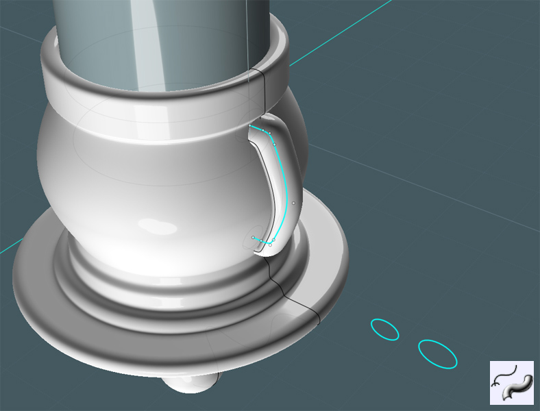
If you place the profile shapes for the Sweep below and away from the imaginary boundary box of the rail curve then MoI will take those shapes, one by one - as arranged and performs a Sweep merging the shapes along the path.


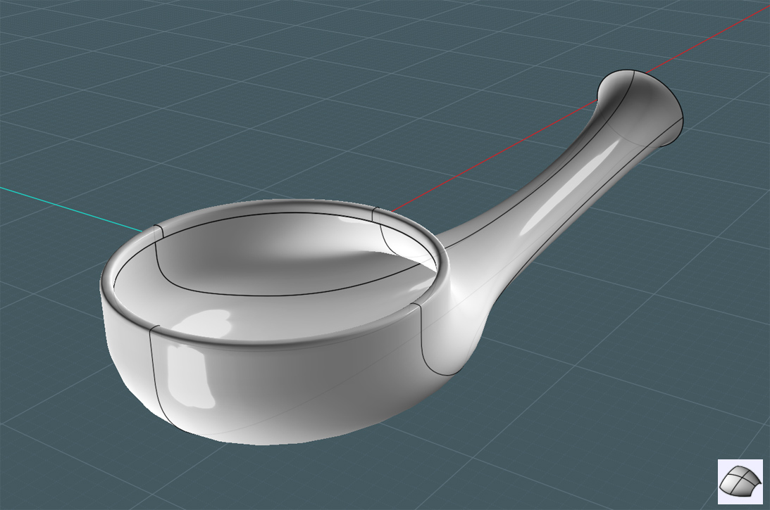
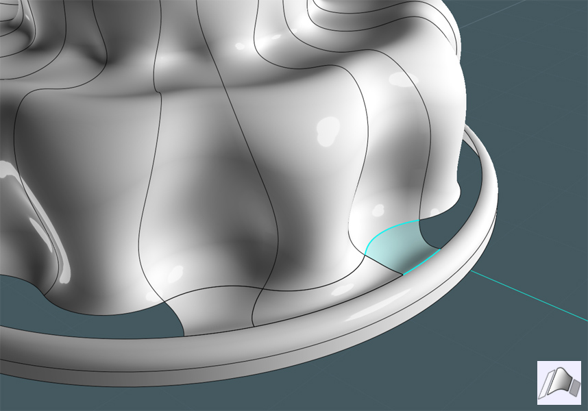
Here I then did three things:
1) I moved the Swept shape so that it sunk a little into the revolved object.
2) I performed a Circular Array to the shape around the revolved object.
3) I Boolean Differenced the main revolved object away from the Swept shapes, leaving curved surfaces.


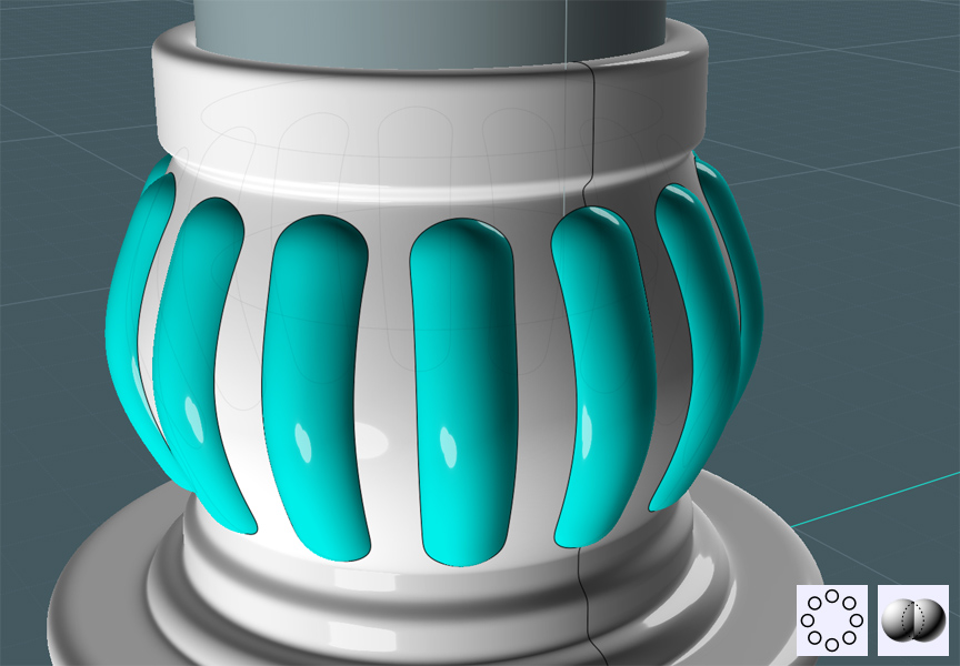
You can simply Boolean Union the Swept shapes to the Revolve shape - then Fillet their edges.
But the Fillets didn't work........

I needed to make edge Blends instead.

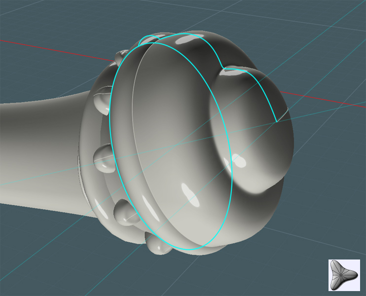
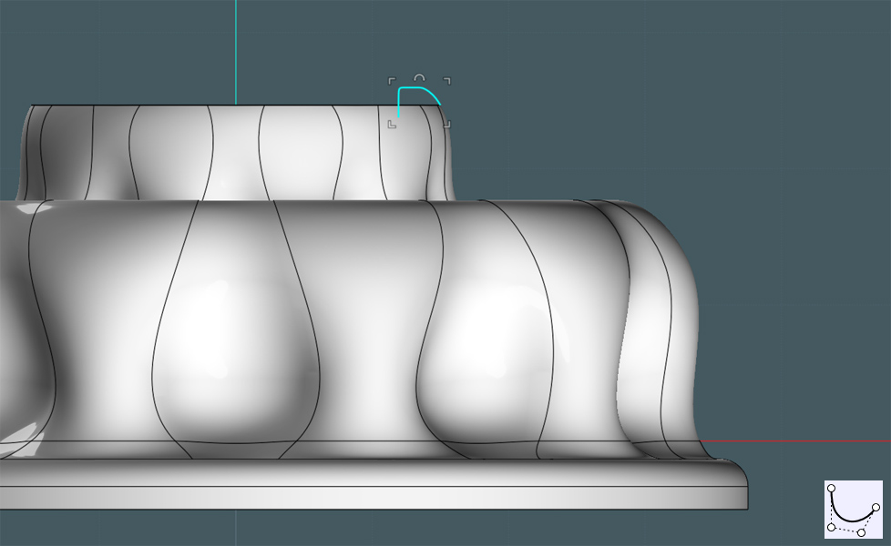
I wanted to make the shapes smaller. So I created a profile curve to act as a cutting shape.
Working in a side view was good for visualizing exact placement.


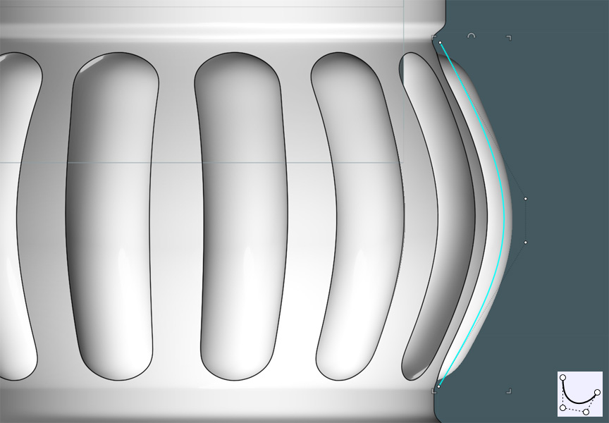
I revolved the profile with the ends capped and trimmed that resultant shape from the curved surfaces.


I failed to show a few steps here, but needless to say, this is up to your own discretion.

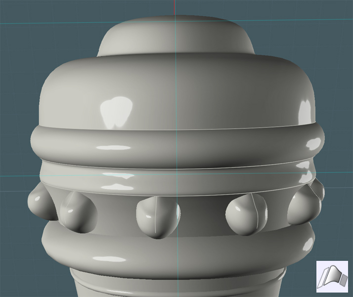
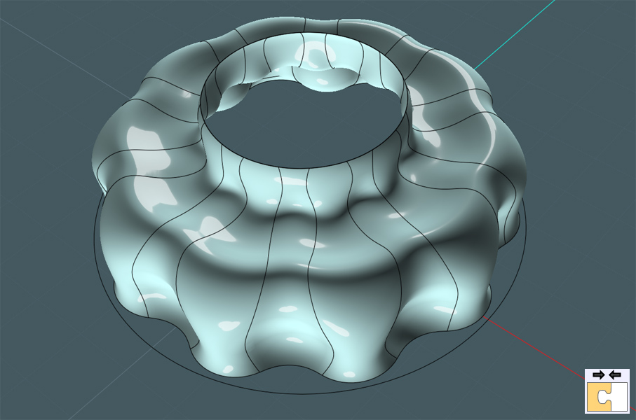
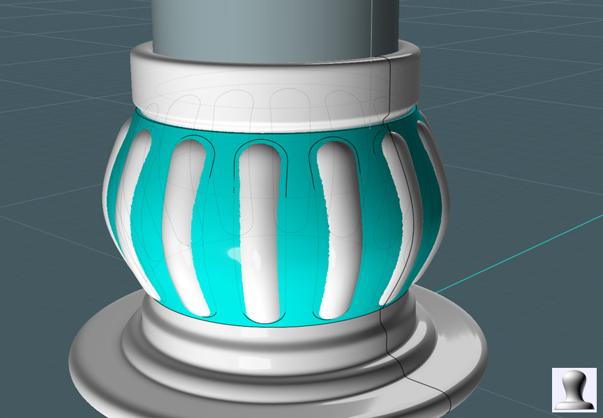
I created a larger (or offset) shape that was also circular-arrayed, Projected and Trimmed from the revolved object's surface.
I then Blended the surface edges of each object.
This gave me a more smooth transition between features.
This was not without trouble as well. I had to both Trim and "Merge" many of the curve segments that were broken up on the edges.


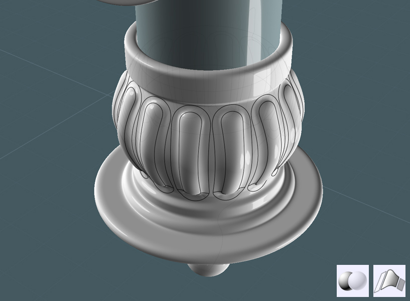
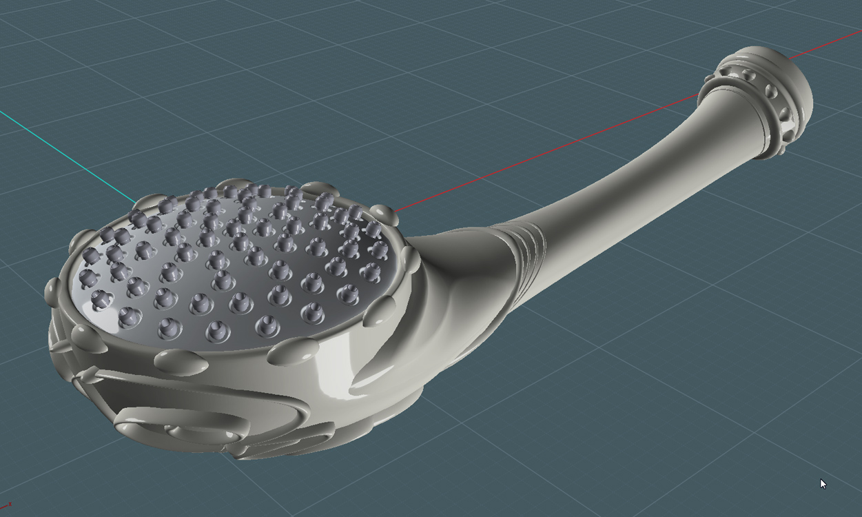
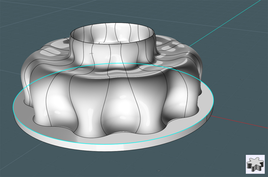
Just simply copy/flip the cap section to the other end of the bar.


Whew!
I had a bit of trouble getting this part done... My home PC had a few technical glitches.
Both a video card and power supply unit had to be replaced! Noooo... I believe the PSU might have ruined the vid card,
or that lightning got both at one time... who knows.
But most likely - it was a lethal combination of NEGLECT and the caking of dust! The poor ventilation and 24/7 operation may not have helped much either. :-o

None the less -


In the next one or two sections I'd like to finish up the shower head model with some extra details being added to the frame.
And also, the modeling of the helical metal water supply hose.

Then later a few good renders after I model up some control fixtures.


Please Visit http://k4icy.50webs.com/tutorials.html for more Tutorials!

EDITED: 29 Nov 2011 by MAJIKMIKE

  Reply Reply More Options
Post Options
Reply as PM Reply as PM
Print Print
Mark as unread Mark as unread
Relationship Relationship
IP Logged

Previous
Next
 From:  Marc (TELLIER)
4673.27 
Cool tutorial, thanks Mike!

Marc
  Reply Reply More Options
Post Options
Reply as PM Reply as PM
Print Print
Mark as unread Mark as unread
Relationship Relationship
IP Logged

Previous
Next
 From:  Frenchy Pilou (PILOU)
4673.28 
works also for curtain rod! ;)
  Reply Reply More Options
Post Options
Reply as PM Reply as PM
Print Print
Mark as unread Mark as unread
Relationship Relationship
IP Logged

Previous
Next
 From:  Rich_Art
4673.29 In reply to 4673.26 
Respect.. really cool design. Thanks again for the tutorial..

Peace,
Rich_Art. ;-)

| C4DLounge.eu | Our Dutch/Belgium C4D forum. Cinema4D R13 Studio + VrayForC4D + UVLayout Pro + 3DCoat
  Reply Reply More Options
Post Options
Reply as PM Reply as PM
Print Print
Mark as unread Mark as unread
Relationship Relationship
IP Logged

Previous
Next
 From:  Mauro (M-DYNAMICS)
4673.30 
Thanks for sharing..plumber Mike...!!
  Reply Reply More Options
Post Options
Reply as PM Reply as PM
Print Print
Mark as unread Mark as unread
Relationship Relationship
IP Logged
 

Reply to All Reply to All


Show messages:  1-10  11-30  31-37