a variable radius or chamfer?
 1-2  3-22  23-31

Previous
Next
 From:  Michael Gibson
4607.3 In reply to 4607.1 
Hi Asanty,

> Hi Michael, how to make a variable radius or chamfer?

MoI does not currently have a variable radius fillet or chamfer tool - that is something that I want to work on adding in for v3.

Currently you would have to do something like build up some profiles and do a sweep or some other surface construction technique like that. Or really the best way currently is to export your model to some other CAD program that does do variable radius fillets, perform the fillet there, and then import it back into MoI. ViaCAD (http://www.punchcad.com/c-12-consumer-cad.aspx) can be an inexpensive companion program to use for that purpose.

- Michael
  Reply Reply More Options
Post Options
Reply as PM Reply as PM
Print Print
Mark as unread Mark as unread
Relationship Relationship
IP Logged

Previous
Next
 From:  Rich_Art
4607.4 In reply to 4607.3 
>>>>
MoI does not currently have a variable radius fillet or chamfer tool - that is something that I want to work on adding in for v3.
<<<<

That sounds great Michael..


Peace,
Rich_Art. ;-)
  Reply Reply More Options
Post Options
Reply as PM Reply as PM
Print Print
Mark as unread Mark as unread
Relationship Relationship
IP Logged

Previous
Next
 From:  Mike K4ICY (MAJIKMIKE)
4607.5 
Asanty,

For those intrigued by the notion:
Here is a mini-tutorial on how to get the result you want using manual methods.
I've seen this done in a few Rhino tutorials.

It's a "Manual Fillet" :-)


Sometimes effective use of the Fillet tool is impossible given complication such as uneven adjoining surfaces, sharp angles, broken edge curves, tiny surfaces in the way and etc.


To make a "manual fillet" do the following:

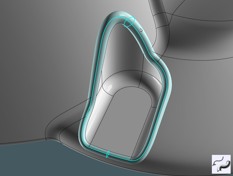
1) Select the desired edge curves and Join to make a separate path.
It can be closed or open. If open, extend the lines a little to clear the objects a little.


2)You need to make a swept shape along the path from profiles.
To do this, create circle profiles to represent the gap (or fillet size) that you want in each of the areas on the path.
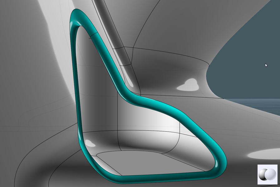
3) Use the Orient command to position the profile circles, so that they'll be perpendicular on the path.


4) Sweep the profiles.
Note, when sweeping a profile along a path - if the path has too sharp a bend to accommodate the profile sweep without "kinking" - you must do separate surgery on the sweep object, by Boolean-differencing (or cutting out) the bad kinked corner and performing a Blend on the edges of the cut area to create a new bend for the sweep.


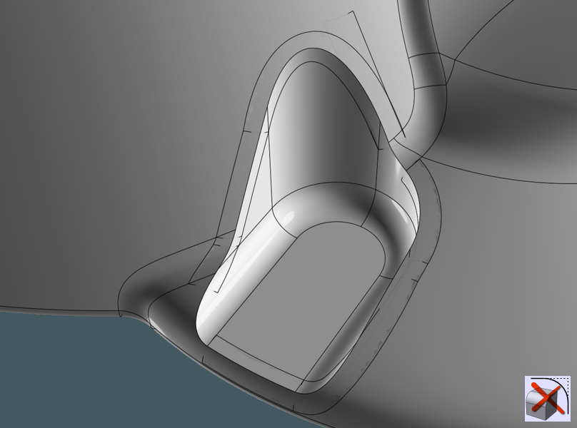
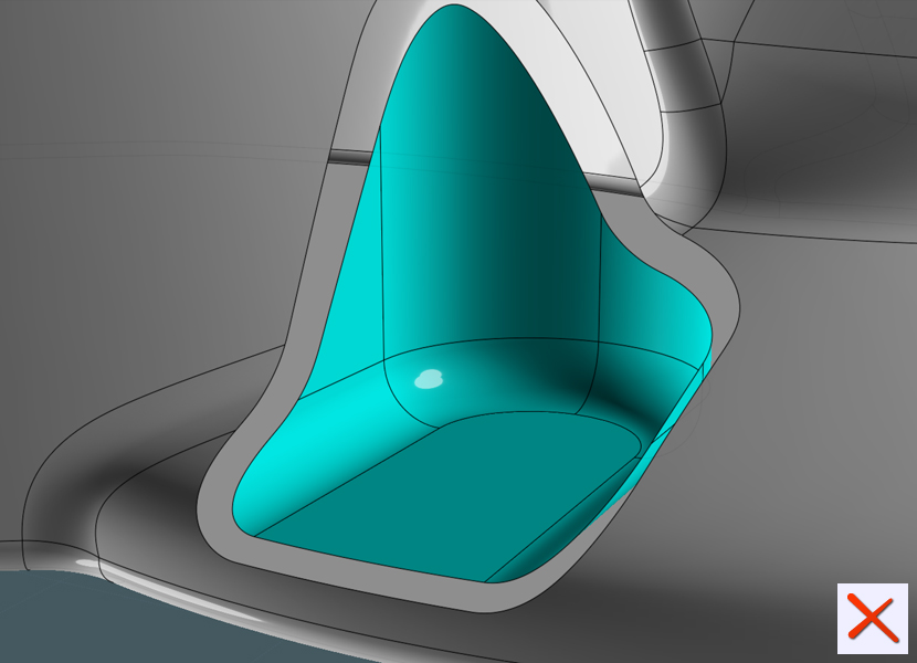
5) Boolean Difference the swept shape from the target surface object.
If all you need is a "Chamfer", congratulation - here you go.
But if you need a nice fillet....


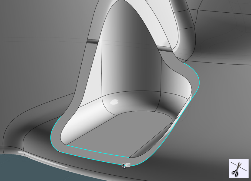
6) Delete the leftover chamfer surface.


To maked blends between the surface edges to both parts of the target surface the curve segments need to be roughly oriented to each other... or in other words, the cuves need to match.
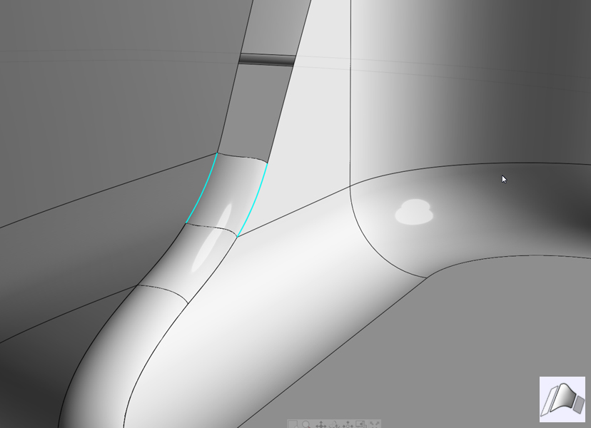
7) Trim the surface curves where needed with the Trim command to break them apart.
They'll still be attached to their surfaces.


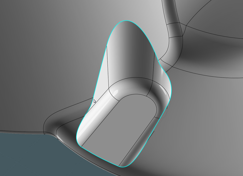
8) Blend these surfaces...


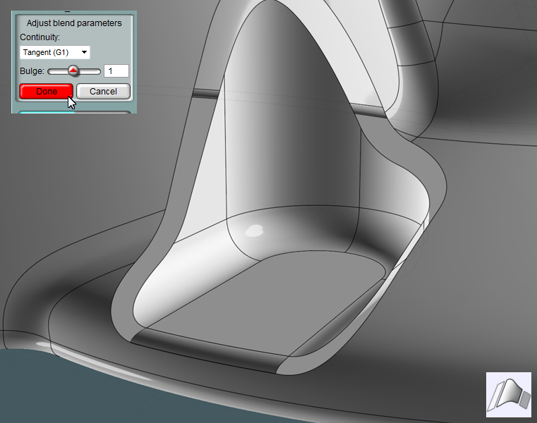
Note how their edges are wavy. Most of the time these wavy edges will match up.
You must handle each intersecting path as the end of every blend section.
(At least until V3)


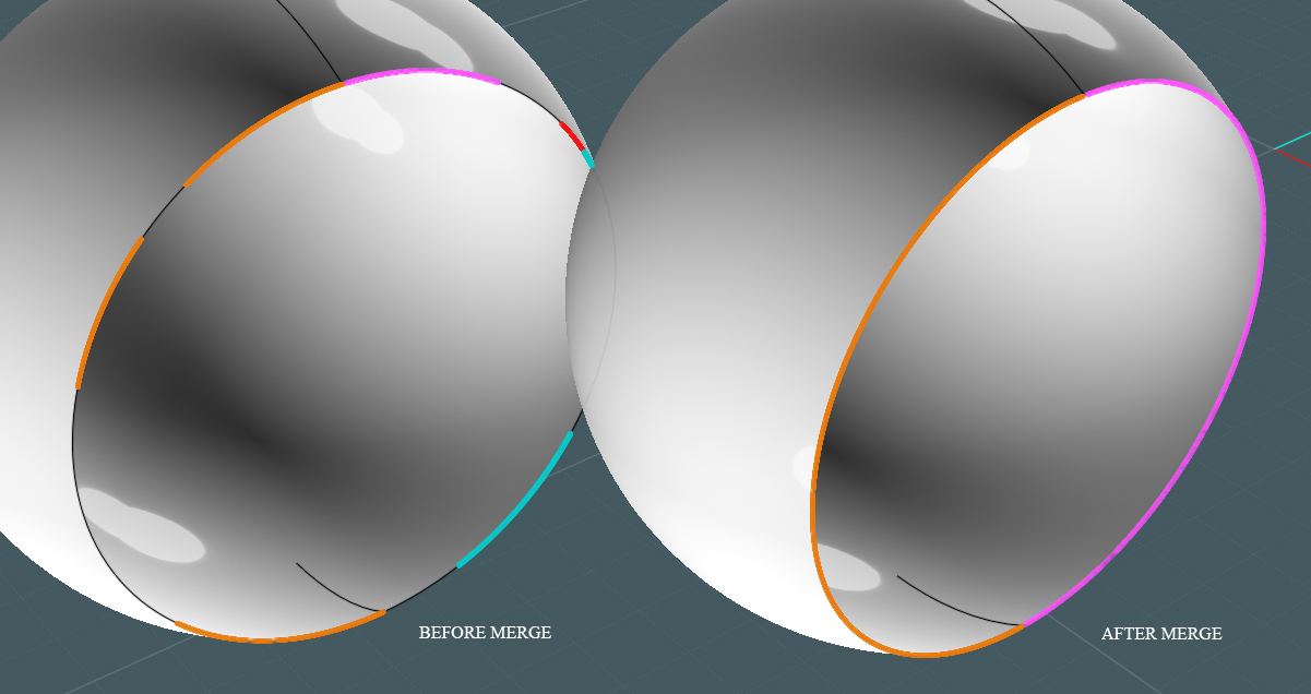
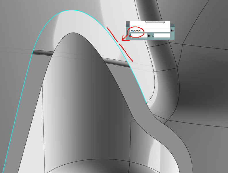
9) Many times you'll have edge curves that are broken into segments.
You must run the non-UI command "Merge" when the broken segments are selected.
This will not combine segments that are intersected by off paths.


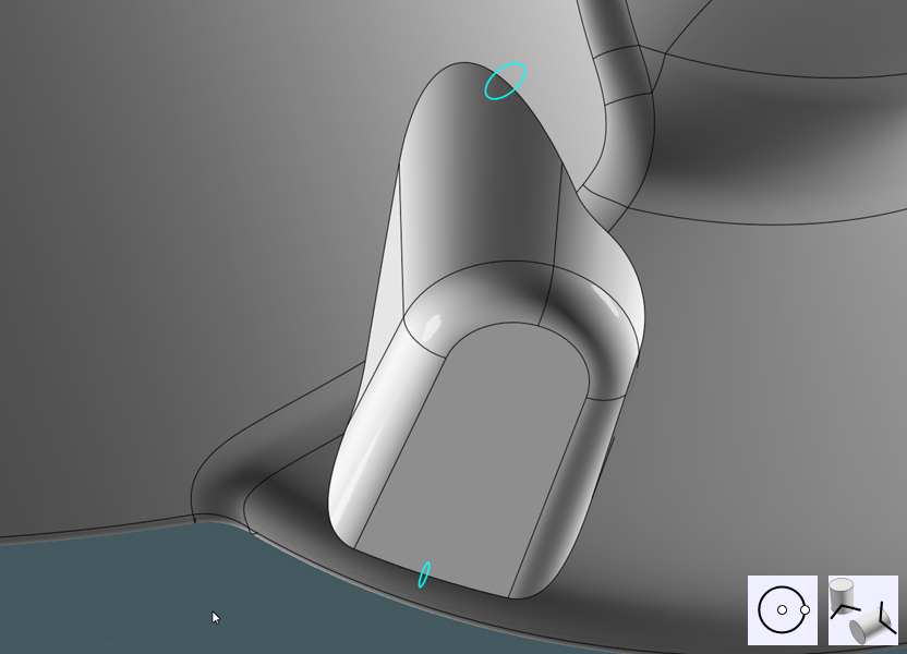
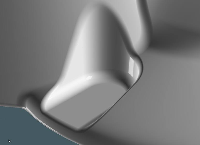
10) Join all surfaces...
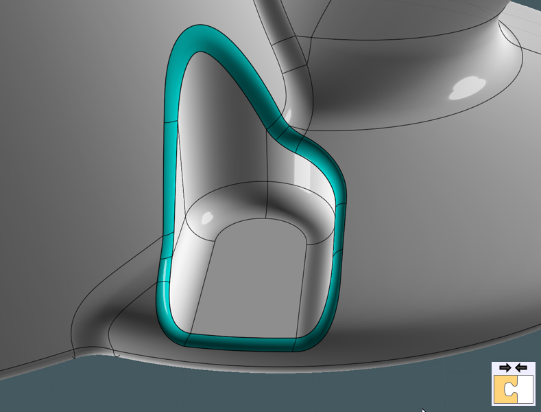


Look at that!
A nice and smooth variable-radius fillet that exists in even the most complicated target surface conditions.


A note to Michael: In my mind, I keep thinking that there may be some way to automate this, or for there to be a function that has the ability to blend the two paths set X-distance from a targeted edge or path on a surface. Then a souped-up Blend operation as shown above would negotiate the multiple broken segments an such, so that the desired result could be achieved - thus, the super-fillet.

However, I completely understand the daunting limitations of space and time, or the many complexities of programing with NURBS, this is way easier said than done. ;-)

EDITED: 13 Oct 2011 by MAJIKMIKE

  Reply Reply More Options
Post Options
Reply as PM Reply as PM
Print Print
Mark as unread Mark as unread
Relationship Relationship
IP Logged

Previous
Next
 From:  Frenchy Pilou (PILOU)
4607.6 
Tricky!
---
Pilou
Is beautiful that please without concept!
My Gallery
  Reply Reply More Options
Post Options
Reply as PM Reply as PM
Print Print
Mark as unread Mark as unread
Relationship Relationship
IP Logged

Previous
Next
 From:  Rich_Art
4607.7 In reply to 4607.6 
nice....

Peace,
Rich_Art. ;-)

| C4DLounge.eu | Our Dutch/Belgium C4D forum. Cinema4D R13 Studio + VrayForC4D + UVLayout Pro + 3DCoat
  Reply Reply More Options
Post Options
Reply as PM Reply as PM
Print Print
Mark as unread Mark as unread
Relationship Relationship
IP Logged

Previous
Next
 From:  Shaun (MOISHAUN)
4607.8 
Tried this on a few models. The problem is after I difference away the sweep the curves left on the shapes I need are broken into pieces. Is there a way to Join them and still have them be part of the surface? When I do a normal Join it makes a brand new curve that won't work for the Blend.

thanks
  Reply Reply More Options
Post Options
Reply as PM Reply as PM
Print Print
Mark as unread Mark as unread
Relationship Relationship
IP Logged

Previous
Next
 From:  Mike K4ICY (MAJIKMIKE)
4607.9 In reply to 4607.8 
Shaun, select all those broken segments on the surface edge and enter the command "Merge"
It will turn them into a solid curve that is still integral to the surface edge.
You cannot Merge around "T" lines that intersect the edge.
But to make things faster, you can grab ALL of the segments and Merge at once will combine each total selection of broken curves within their own respective surface together, separated of course by the "T" intersections.
To cut them back up ANYWHERE, use Trim and "Add Trim Points"

EDITED: 14 Oct 2011 by MAJIKMIKE

  Reply Reply More Options
Post Options
Reply as PM Reply as PM
Print Print
Mark as unread Mark as unread
Relationship Relationship
IP Logged

Previous
Next
 From:  BurrMan
4607.10 In reply to 4607.9 
You can also just select your model and run Merge to do all at once.
  Reply Reply More Options
Post Options
Reply as PM Reply as PM
Print Print
Mark as unread Mark as unread
Relationship Relationship
IP Logged

Previous
Next
 From:  Shaun (MOISHAUN)
4607.11 
I mean say you trim a curve attached to a surface. Is there a way to un-trim it and keep it part of the surface?
  Reply Reply More Options
Post Options
Reply as PM Reply as PM
Print Print
Mark as unread Mark as unread
Relationship Relationship
IP Logged

Previous
Next
 From:  Mike K4ICY (MAJIKMIKE)
4607.12 
Shaun - This is what I was talking about.

  Reply Reply More Options
Post Options
Reply as PM Reply as PM
Print Print
Mark as unread Mark as unread
Relationship Relationship
IP Logged

Previous
Next
 From:  Shaun (MOISHAUN)
4607.13 In reply to 4607.12 
Ahhh! I thought you meant boolean merge. I found it.

thanks
  Reply Reply More Options
Post Options
Reply as PM Reply as PM
Print Print
Mark as unread Mark as unread
Relationship Relationship
IP Logged

Previous
Next
 From:  Michael T. (MICTU_UTCIM)
4607.14 
I use ViaCAD 2D/3D as Michael G. stated and it is an excellent companion for MoI. I originally bought it for making 2D drawings of my MoI models, and realized it woorks great for the variable fillets you are looking for, but is also useful for adding draft and keeping all of these things editable as well.

I use MoI with ViaCAD 2D/3D for all of my freelance design work. A winning combo!

Michael T.
Michael Tuttle a.k.a. mictu http://www.coroflot.com/DesignsByTuttle
  Reply Reply More Options
Post Options
Reply as PM Reply as PM
Print Print
Mark as unread Mark as unread
Relationship Relationship
IP Logged

Previous
Next
 From:  mariomarimba
4607.15 In reply to 4607.5 
HI MAGIC
how do you get this shiny shaded look on your models??

regards

mario
  Reply Reply More Options
Post Options
Reply as PM Reply as PM
Print Print
Mark as unread Mark as unread
Relationship Relationship
IP Logged

Previous
Next
 From:  Mike K4ICY (MAJIKMIKE)
4607.16 In reply to 4607.15 
Try this lighting setup MarioMarimba:

  Reply Reply More Options
Post Options
Reply as PM Reply as PM
Print Print
Mark as unread Mark as unread
Relationship Relationship
IP Logged

Previous
Next
 From:  Rich_Art
4607.17 In reply to 4607.16 
I tried your cool scheme on the v3 beta but it won't work for me..

Peace,
Rich_Art. ;-)

| C4DLounge.eu | Our Dutch/Belgium C4D forum. Cinema4D R13 Studio + VrayForC4D + UVLayout Pro + 3DCoat
  Reply Reply More Options
Post Options
Reply as PM Reply as PM
Print Print
Mark as unread Mark as unread
Relationship Relationship
IP Logged

Previous
Next
 From:  Mike K4ICY (MAJIKMIKE)
4607.18 In reply to 4607.17 
Rich_Art,

The lighting settings work on my copy of V3, you have to manually enter one or two of the numbers as the sliders have a fixed range.
but no, the custom UI I made won't work outright in V3.
I'm not going to try to set it up again until the arrival of the final V3. And if Michael has made special permanent changes to the way the icons, commands and general UI system works, ...then I'll have to cross that bridge when I get to it.
  Reply Reply More Options
Post Options
Reply as PM Reply as PM
Print Print
Mark as unread Mark as unread
Relationship Relationship
IP Logged

Previous
Next
 From:  Rich_Art
4607.19 In reply to 4607.18 
Yeah I can only say, you're right. But I love the layout/scheme.. The lighting settings works indeed. It was one of the first things I adapted when I installed V3 beta. :-)
I already thanked you for this but I do it again. Thanks. :-))

Peace,
Rich_Art. ;-)

| C4DLounge.eu | Our Dutch/Belgium C4D forum. Cinema4D R13 Studio + VrayForC4D + UVLayout Pro + 3DCoat
  Reply Reply More Options
Post Options
Reply as PM Reply as PM
Print Print
Mark as unread Mark as unread
Relationship Relationship
IP Logged

Previous
Next
 From:  Mike K4ICY (MAJIKMIKE)
4607.20 In reply to 4607.19 
Cool. :-)


Michael, do you plan on making V3's UI customizable as well?
  Reply Reply More Options
Post Options
Reply as PM Reply as PM
Print Print
Mark as unread Mark as unread
Relationship Relationship
IP Logged

Previous
Next
 From:  Michael Gibson
4607.21 In reply to 4607.20 
Hi Mike,

> Michael, do you plan on making V3's UI customizable as well?

Well, it already is in the same sense as V2's was - the UI is still all made up of stuff that's in the \ui sub-folder.

The way it is all set up is a little different than v2 though - in v3 things like rounded corners and buttons come from various parameters (like gradients and border-radius values) that are declared in the moi.css file rather than having all those different things come just from images.

So for example the way a button is defined is all contained in the moi.css file in the PushButton section there, there aren't any bitmap images used for a button anymore. That should make it easier to do things like change colors to different themes since the color can be changed just by changing a numeric rgb value rather than having to make a new custom image for every UI element.

So it's a bit different strategy and setup than how V2/V1 was using though.

I still plan on making some changes in this area - I'll probably be making a system so that the colors in moi.css will get replaced by some kind of labels and there will be another separate file that defines the color for each label. Then it will be possible to change colors just by changing that color definition file and it should make it easier to have some different color themes to switch between which will switch between different color definition files. This part is still to come though.

So anyway there will still be some more changes coming in this area, so it's probably not a great idea to invest a whole lot of time in it just yet.

- Michael
  Reply Reply More Options
Post Options
Reply as PM Reply as PM
Print Print
Mark as unread Mark as unread
Relationship Relationship
IP Logged

Previous
Next
 From:  Mike K4ICY (MAJIKMIKE)
4607.22 In reply to 4607.21 
Very good then.

But from what you're saying then, I'll be able to customize the color of the buttons, but I won't be able to use the nifty glossy custom bitmap button components I use now?
Okay. :-|

Might I make a suggestion, that the ability to change the (basic) color scheme across the board, such as the buttons color, UI background and basic type, could be changed via color picker in the options dialog as we can change the grid and 3D view backgrounds now.
  Reply Reply More Options
Post Options
Reply as PM Reply as PM
Print Print
Mark as unread Mark as unread
Relationship Relationship
IP Logged
 

Reply to All Reply to All


Show messages:  1-2  3-22  23-31