SMA Connector
All  1  2-7

Previous
Next
 From:  Mike K4ICY (MAJIKMIKE)
4594.2 In reply to 4594.1 
(Woop!!) (Whistle!!) Take it off! Show us your PL-259! :-D

That's eye-candy to hams like me.

Good job OSTexo, those connectors look nice!
  Reply Reply More Options
Post Options
Reply as PM Reply as PM
Print Print
Mark as unread Mark as unread
Relationship Relationship
IP Logged

Previous
Next
 From:  twofoot
4594.3 In reply to 4594.1 
Nice render!
  Reply Reply More Options
Post Options
Reply as PM Reply as PM
Print Print
Mark as unread Mark as unread
Relationship Relationship
IP Logged

Previous
Next
 From:  OSTexo
4594.4 
Hello,

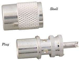
By the way, many images I see show the PL259 (UHF) center pin extending past the body of the connector. The line drawing reference I have for the connector shows the pin being protected slightly by the body. Which way is it? I don't run into the PL259 at all, HAMs know better than I. Thanks.
  Reply Reply More Options
Post Options
Reply as PM Reply as PM
Print Print
Mark as unread Mark as unread
Relationship Relationship
IP Logged

Previous
Next
 From:  Mike K4ICY (MAJIKMIKE)
4594.5 In reply to 4594.4 


The center pin extends from the end of the main body about a half an inch.
The sleeve barrel screws on from the cable side and is not allowed to come off, but when engaged with the SO-239 female part the sleeve roughly matches the position of the center pin.

So the barrel end will start flush with the major base area of the pin, then when connected, the barrel is screwed on to the socket to hold it in place.

Go here:
http://www.rfcoaxconnectors.com/Technical_Interface-drawing.htm

You may find this interesting.
  Reply Reply More Options
Post Options
Reply as PM Reply as PM
Print Print
Mark as unread Mark as unread
Relationship Relationship
IP Logged

Previous
Next
 From:  OSTexo
4594.6 
Hello,

Thanks for the excellent reference and explanation on the UHF connector. I suppose there is some variability in connectors of all types but it's good to know the min/max allowable. Here is the N and SMA together, the SMA looks a little large or the N looks a little small, I'll have to recheck my measurements in MoI, or maybe it's my environment / camera settings in Thearender. The inner ring and screw threads look a little thick on the N type, I think I'll tweak those and put in a few more fillets to catch the light.

Attachments:

  Reply Reply More Options
Post Options
Reply as PM Reply as PM
Print Print
Mark as unread Mark as unread
Relationship Relationship
IP Logged

Previous
 From:  WillBellJr
4594.7 
NICE!

I haven't seen an SMA connector since my electronic engineering days back in the '90s work on high speed, emitter-coupled logic circuits!

Brings back memories...

-Will
  Reply Reply More Options
Post Options
Reply as PM Reply as PM
Print Print
Mark as unread Mark as unread
Relationship Relationship
IP Logged
 

Reply to All Reply to All


Show messages: All  1  2-7