Flow
 1-20  21-30

Next
 From:  Marc (TELLIER)
4442.1 
Hi,

Flow is quite awesome, however on surfaces I sometime get some unexpected results. In the example below the sphere appears to be squished.

Maybe there is something I miss, perhaps how it is mapped on the target.

Marc


  Reply Reply More Options
Post Options
Reply as PM Reply as PM
Print Print
Mark as unread Mark as unread
Relationship Relationship
IP Logged

Previous
Next
 From:  Mike K4ICY (MAJIKMIKE)
4442.2 
Will changing the relative proportions of the sample square work to change the end result of the squished sphere?


...Okay Marc... the way I've figured it is that the distance span on that that sphere is (Diameter x Pi) for the distance from the BRep line around the equator of the sphere back to the BRep line. And the distance from one pole to the other, at the ends of the BRep line on the sphere is (Diameter x Pi) / 2. A 2 to 1 ratio.

If the Flow command is "fitting" the sample object to the sphere's surface using the sample square as the template, then the smaller sphere will be stretched 2 to 1... You need to scale the sample square horizontally by 2.

Am I correct?

EDITED: 25 Aug 2011 by MAJIKMIKE

  Reply Reply More Options
Post Options
Reply as PM Reply as PM
Print Print
Mark as unread Mark as unread
Relationship Relationship
IP Logged

Previous
Next
 From:  Frenchy Pilou (PILOU)
4442.3 In reply to 4442.1 
Your yellow figure is not a sphere: it's a truncated sphere!
Else result seems normal :)
With a real sphere you obtain that

EDITED: 25 Aug 2011 by PILOU

  Reply Reply More Options
Post Options
Reply as PM Reply as PM
Print Print
Mark as unread Mark as unread
Relationship Relationship
IP Logged

Previous
Next
 From:  Marc (TELLIER)
4442.4 
Hi, thanks for the pointers, I'll check that out!
I'm not very familiar with Brep and stuff...

Marc
  Reply Reply More Options
Post Options
Reply as PM Reply as PM
Print Print
Mark as unread Mark as unread
Relationship Relationship
IP Logged

Previous
Next
 From:  Marc (TELLIER)
4442.5 In reply to 4442.4 
I think I start to get it, the scale of the reference object change the projected result a lot.

I have scale the reference plane down smaller and than the half sphere and it has wrapped around more.
Also using a rectangle is much better in this situation.


I would've expected the distance between the quadrant of the sphere and the edge of the plane to be the same as the quadrant and the seam of the sphere proportionally. Does this makes sense?


Maybe this is a too simple situation?

Marc

  Reply Reply More Options
Post Options
Reply as PM Reply as PM
Print Print
Mark as unread Mark as unread
Relationship Relationship
IP Logged

Previous
Next
 From:  Michael Gibson
4442.6 In reply to 4442.1 
Hi Marc - so the reason why this result is confusing is because flow works on the underlying surfaces, not just on the visible trimmed area.

It looks like your plane was created by using the Construct > Planar command, which builds a trimmed surface and it puts the base underlying plane surface at somewhat larger size than the trim curves.

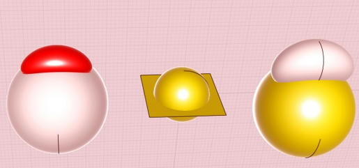
You can see this more clearly if you turn on control points for your base plane - when you do that notice how the underlying plane surface itself is actually a bit larger, like this:


That larger plane where you see the 4 corner control points is the thing that is actually used as the base surface currently, that's why the final result is not at the proportion that you were expecting.

If you use the ShrinkTrimmedSrf command (http://moi3d.com/2.0/docs/moi_command_reference10.htm#shrinktrimmedsrf) on that base plane it will shrink the underlying surface down to be snug to the trimming boundaries and then after that you should see a result more like you would have been expecting.

But also the way flow works is that it basically matches a kind of percentage along each surface, it's not going to do stuff like match a distance from the object to one edge to another distance, it's more like every point on the base plane goes to its equivalent percentage on the target surface.


Hope this helps explain the confusing result - I maybe should make the base and target surfaces automatically shrink down to fit their shaded visible boundaries to avoid this kind of confusing result. At the moment the ShrinkTrimmedSrf command will do that for you.

- Michael

  Reply Reply More Options
Post Options
Reply as PM Reply as PM
Print Print
Mark as unread Mark as unread
Relationship Relationship
IP Logged

Previous
Next
 From:  Mike K4ICY (MAJIKMIKE)
4442.7 In reply to 4442.6 
It's all so clear now! ;-)
  Reply Reply More Options
Post Options
Reply as PM Reply as PM
Print Print
Mark as unread Mark as unread
Relationship Relationship
IP Logged

Previous
Next
 From:  Marc (TELLIER)
4442.8 
Ahh, it all make sense!

I did not know about this particular behavior of the "Construct > Planar command"
I will use "Draw solid>Plane" instead in this situation.

The results looks more of what I expected this way...


Thanks for taking the time to clear this up Michael.

This function opens up a lot of possibilities!

Marc

  Reply Reply More Options
Post Options
Reply as PM Reply as PM
Print Print
Mark as unread Mark as unread
Relationship Relationship
IP Logged

Previous
Next
 From:  Frenchy Pilou (PILOU)
4442.9 
If the start object don't touch the surface, the end object on the target surface don't touch it also
Am i right?

---
Pilou
Is beautiful that please without concept!
My Gallery
  Reply Reply More Options
Post Options
Reply as PM Reply as PM
Print Print
Mark as unread Mark as unread
Relationship Relationship
IP Logged

Previous
Next
 From:  ed (EDDYF)
4442.10 In reply to 4442.9 
I believe that is correct Pilou.

And it also looks like if your text (or start object) intersects the base surface, the result will intersect the target surface as well (rather than sit on top).

Ed
  Reply Reply More Options
Post Options
Reply as PM Reply as PM
Print Print
Mark as unread Mark as unread
Relationship Relationship
IP Logged

Previous
Next
 From:  Michael Gibson
4442.11 In reply to 4442.9 
Hi Pilou,

> If the start object don't touch the surface, the end object on the
> target surface don't touch it also
> Am i right?

Yup, that's correct - the same distance of the start object to the base object will be applied to the target surface.

It's related to surface offsetting really - basically the distance of the starting object to the base surface becomes an offset distance that is used to make a point on an offset surface of the target surface.

- Michael
  Reply Reply More Options
Post Options
Reply as PM Reply as PM
Print Print
Mark as unread Mark as unread
Relationship Relationship
IP Logged

Previous
Next
 From:  Michael Gibson
4442.12 In reply to 4442.10 
Hi Ed,

> And it also looks like if your text (or start object) intersects
> the base surface, the result will intersect the target surface as
> well (rather than sit on top).

Yup, that's correct too.

Also if you plan to boolean the resulting objects on to the target, it's probably best to make them intersect it a bit (like pushing down through it somewhat) rather than making them just skim right along the same surface area. That kind of barely skimming situation tends to be harder for the booleans to deal with.

If the booleans seem to get confused also try doing the boolean between 2 pieces at a time rather than as a whole group. Sometimes that can help - at some point I want to track that down and figure out why that helps in some kinds of situations.

- Michael
  Reply Reply More Options
Post Options
Reply as PM Reply as PM
Print Print
Mark as unread Mark as unread
Relationship Relationship
IP Logged

Previous
Next
 From:  ed (EDDYF)
4442.13 In reply to 4442.12 
Here's a Flow test using text and a cylinder. The text intersects the base surface causing it to intersect the target surface. Joined cylinder surfaces to make a solid and Boolean diff to create engraved text. Quick render shown in corner.

"... I maybe should make the base and target surfaces automatically shrink down to fit their shaded visible boundaries to avoid this kind of confusing result."

Please do. This really messed me up until I read the explanation and fix. Guaranteed it will mess me up again :)

Ed

Attachments:

  Reply Reply More Options
Post Options
Reply as PM Reply as PM
Print Print
Mark as unread Mark as unread
Relationship Relationship
IP Logged

Previous
Next
 From:  Michael Gibson
4442.14 In reply to 4442.13 
Hi Ed - by the way you can leave the cylinder to be a joined up solid from the start if you want. You can pick a face out of a joined solid as the target surface for the flow.

- Michael
  Reply Reply More Options
Post Options
Reply as PM Reply as PM
Print Print
Mark as unread Mark as unread
Relationship Relationship
IP Logged

Previous
Next
 From:  BurrMan
4442.15 In reply to 4442.14 
There may be some benefit to the ability to still flow to the full underlying surface..
  Reply Reply More Options
Post Options
Reply as PM Reply as PM
Print Print
Mark as unread Mark as unread
Relationship Relationship
IP Logged

Previous
Next
 From:  Michael Gibson
4442.16 In reply to 4442.15 
Hi Burr,

> There may be some benefit to the ability to still flow
> to the full underlying surface..

If there was built-in shrinking, you could still get the same current result with using the full surface by doing an "untrim" on the surface first before using it as the base or target surface for Flow.

- Michael
  Reply Reply More Options
Post Options
Reply as PM Reply as PM
Print Print
Mark as unread Mark as unread
Relationship Relationship
IP Logged

Previous
Next
 From:  Mike K4ICY (MAJIKMIKE)
4442.17 
I am so jealous! ;-)
  Reply Reply More Options
Post Options
Reply as PM Reply as PM
Print Print
Mark as unread Mark as unread
Relationship Relationship
IP Logged

Previous
Next
 From:  BurrMan
4442.18 In reply to 4442.16 
It could be useful to not have to disassemble the model to have the option.... (buttons, buttons, tick mark 1, 2 and 3 Burr)
  Reply Reply More Options
Post Options
Reply as PM Reply as PM
Print Print
Mark as unread Mark as unread
Relationship Relationship
IP Logged

Previous
Next
 From:  Michael Gibson
4442.19 In reply to 4442.18 
Hi Burr,

> It could be useful to not have to disassemble the model to have the option....

You wouldn't necessarily have to disassemble it and reassemble it again - select the piece you want and do Ctrl+c to copy it to the clipboard, then hide the full model and paste in the piece that you'll modify and throw away when you're finished. Meanwhile the original piece stays as one whole thing so you don't have to reassemble stuff.

Let me know if you end up doing that frequently and those steps could likely be automated with a script of some kind.

On the other hand if it's something that you only need to do every once in a while then doing 3 steps or so instead of a having special option is not really a problem.

I know you guys like to have things done in fewer steps, but there is a tradeoff - it's not very good if you are presented with a giant panel of options making things look like a 747 control panel even if each button does some cool combination of what would otherwise take a couple of steps. When the UI gets clogged up with a ton of stuff a whole lot of other people aren't able to just run the basic stuff anymore because things tend to get lost in the mess.

But if there are things that you end up doing repeatedly in sequence, I can most likely cook up a plug-in that will help to streamline it for you.

- Michael
  Reply Reply More Options
Post Options
Reply as PM Reply as PM
Print Print
Mark as unread Mark as unread
Relationship Relationship
IP Logged

Previous
Next
 From:  BurrMan
4442.20 In reply to 4442.19 
Ahahahhaaaa.. Short sightedness... I didnt even contemplate a simple copy and paste... Seems to solve it fairly well!!! :o
  Reply Reply More Options
Post Options
Reply as PM Reply as PM
Print Print
Mark as unread Mark as unread
Relationship Relationship
IP Logged
 

Reply to All Reply to All


Show messages:  1-20  21-30