Make It With MoI
 1-20  21-40  41-60  …  161-174
Thread Split: Some posts in this thread have been moved here

Next
 From:  Mike K4ICY (MAJIKMIKE)
4388.1 
Hi all,

Since I have some time before I can purchase V2...
Using the No-Save trial will allow me to focus on smaller, experimental models.
I'll get a chance to learn MoI's features more keenly, develop workflows, and just plain make interesting stuff.

I invite others to comment, provide solutions and add their own neat models.


My wife uses this Swiffer broom thing and I took a look at the organic looking handle on top... The more I looked at it, the more I realized that it had some thought put into it.


I spent a little time the other day putting together this model to see if I could reproduce this shape in MoI.
I thought it would be simple, It's just a bulb shape that has a ring on it, but not only does the hanging ring "melt" into the handle grip, but it is tapered.
I noticed that everything was a generally a perfect tangent also. A perfect use for NURBS.
1) I swept a circle around a large circle to produce a torus shape. It was also tapered by moving a copy of the large ring on top and slanting it down on one side, using it as a Scaling Rail.
2) I cut out a chunk of the bottom of the ring to create a shape to merge to.
3) I created profiles for a network. I then Joined the ring and network mesh together.


However. I still don't know a better way to make a whole and seamless creation.
You can see the irregularities in the connection between the two objects.


I tried different configurations of the Blend tool, but there are overriding tangents and a strange shape transition from a more rectangle shape to a circle along the neck.

Consequently, I did a Google search today for a pic of the handle, and actually found the guy that created this thing for the Swiffer company.
He lists that he uses Alias and Solid Works for his modeling. Alias is an Autodesk app - and one of a dozen or less devoted to one small aspect of 3D modeling.
My mind just boggled over the complexity of software solutions required to do this kind of work. Many apps duplicating the same features.

Simple is sometimes better -
...Even though I have a good 20+ years of graphics experience and training. 3D design is new to me, and with just a few weeks of using MoI, a 10 meg app.
I was able to potentially re-create something made with a multi-thousand dollar specialty app.
I know MoI should be thought of as an extension to one's favorite apps, and that companies with large wallets and specialized milling machines need specialized stuff.
But, if a designer wants to see something from nothing quick, and wants to have the uninhibited freedom to create good stuff without being bogged down by a zillion buttons and sub-menus,
MoI is it!

I'm excited to see what lies in store for MoI's future.
More power to you Michael!

Thanks!

(I'll post more in this thread)

EDITED: 6 Aug 2011 by MICHAEL GIBSON


  Reply Reply More Options
Post Options
Reply as PM Reply as PM
Print Print
Mark as unread Mark as unread
Relationship Relationship
IP Logged

Previous
Next
 From:  Michael Gibson
4388.2 In reply to 4388.1 
Thanks Mike, I'm glad that you're continuing to have fun using MoI!

For things that look all very melty and blobby there is a completely different kind of modeling technology called subdivision surfaces which can be a good fit for very organic shapes that are not driven so much by distinct profile curves.

If that's the kind of shape that you're going to be often focused on building, then using a modeler that is based off of that sub-d modeling technology can work better for those particular kinds of models.

You might want to check out T-splines (http://www.tsplines.com/) or Modo (http://www.luxology.com/) for a couple of examples on some modeling system that are more specifically focused on that style of modeling.

Also check out here for an overview video of that style of modeling:
http://www.youtube.com/user/GuerrillaCG#p/a/u/2/ckOTl2GcS-E

There can be a pretty high learning curve with sub-d modeling though, because it's basically focused on managing a whole lot of vertex placement in 3D space, so you have to learn techniques for how to manage a bunch of vertices well, like the best ways to arrange topology and stuff like that.


But there are actually quite a variety of different kinds of modeling technology, and some particular kinds of technologies tend to be well suited for some particular styles of models.

MoI is basically more optimized for the kind of model that is more structurally defined by some profile curves - things that are blobby and melty are not really much like that though.

- Michael
  Reply Reply More Options
Post Options
Reply as PM Reply as PM
Print Print
Mark as unread Mark as unread
Relationship Relationship
IP Logged

Previous
Next
 From:  Mike K4ICY (MAJIKMIKE)
4388.3 In reply to 4388.2 
Hi Michael,

The video was educational. Modo is one of the kings of Sub-D and the movie industry goes ga-ga for it.
And if I'm correct, T-Splines is NURBS on steroids. All types with their strong points.

I've got confidence in MoI!
Especially concerning product creation and mechanical visualization.
I love the concept of NURBS, just a few coordinates expressing fluid shapes with exacting accuracy.

Thanks !


The MACH-16 wet razor. Not only the closest shave, it goes ahead and takes care of next week's whiskers....
Took about half an hour.


  Reply Reply More Options
Post Options
Reply as PM Reply as PM
Print Print
Mark as unread Mark as unread
Relationship Relationship
IP Logged

Previous
Next
 From:  eric (ERICCLOUGH)
4388.4 In reply to 4388.3 
Hi Magic Mike

If I shaved I would be standing in line for one of those.

cheers,
eric
  Reply Reply More Options
Post Options
Reply as PM Reply as PM
Print Print
Mark as unread Mark as unread
Relationship Relationship
IP Logged

Previous
Next
 From:  Mike K4ICY (MAJIKMIKE)
4388.5 In reply to 4388.4 
Thanks!

Never used a non-electric razor myself... too chicken.

Close-up detail...


Have to push the 'New' button soon... She was a good model. :-)
Attachments:

  Reply Reply More Options
Post Options
Reply as PM Reply as PM
Print Print
Mark as unread Mark as unread
Relationship Relationship
IP Logged

Previous
Next
 From:  3DKiwi
4388.6 
Fabulous work. Well done :)
Homepages: 3dkiwi.co.nz & C4D Cafe
  Reply Reply More Options
Post Options
Reply as PM Reply as PM
Print Print
Mark as unread Mark as unread
Relationship Relationship
IP Logged

Previous
Next
 From:  Mike K4ICY (MAJIKMIKE)
4388.7 
For today's lesson, I'd like to show the use of Sweep and Network...


For a few months now, I wanted to model this glass and chrome bathroom container I own.

(I was using SketchUp among other applications I tried, but was not able to recreate this seemingly simple object)


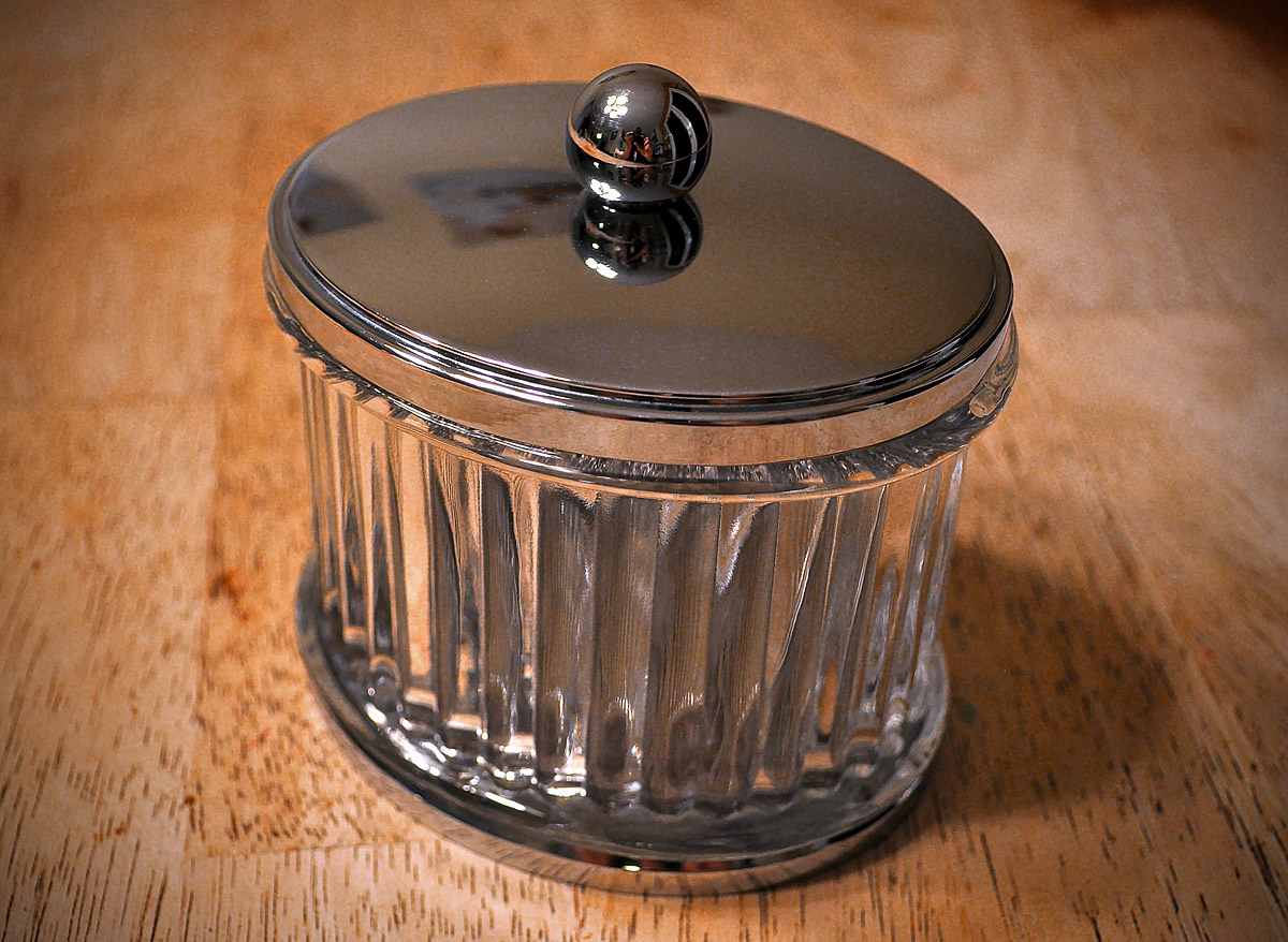
So now after learning MoI, being able to actually create this now with MoI has special meaning to me.

I tried to create this in SketchUp, but had no success for two reasons:
1) The overall shape of the container was not an oval, but a super-ellipsoid, or in other words, a more squarish shaped oval.
2) The lid has a dome shape. Yes, you can sweep a dome shape easily. But this one was swept around the ellipsoid and was not possible in SketchUp.
3) There are plug-ins to handle things like loft and sweep, but upon closer inspection of the glass, there were smooth transitions - or fillets. Too many bad things outweighed the benefits.

My goal is/was to render a model of this, including the chrome and glass elements. Add some nice light and maybe put something colorful inside.

Then came MoI and NURBS... yes! Maybe I could use the Sweep on Rail tool, and fillets are now possible!


The following is a step by step:


This is the finished model. I could render this in glass and chrome. It consists of a glass enclosure, a metal pan on the bottom and a metal lid.


Use the Conic tool to get a nice "squarish-oval" quadrant.
Pull some construction guides horizontally and vertically - place two diagonal corner points, then place an intersecting point in the opposite corner and click to place and shape the desired Conic curve.
Note: This arrangement keeps the ends perfectly tangent with their associated quadrant Conic curves.


Copy or Mirror, then Join to make the super-ellipsoid shape.


Go to a side view and draw the desired profile shape to suit, and go from the outer edge of ellipsoid shape to the center.
Here, I drew a more intricate stepped lip edge using a single session with the Freeform Bezier tool.
I wanted no edge rings, or the possibility of those darned seams. Plus, a few subtle undulations in the surface may yield a more man-made look in the final solid.

Note: Whenever you place the second point of a spline curve in tangent with the curve it is adjacent to it (that it's connecting too), you'll have a smooth transition between the two curves. Note the pic where the top of the dome is to be formed. The second point is in line with not only the end point but the second point in the curve to follow it.
Also, if you add more than two points in a straight line, you'll form a (virtual) straight line in your spline. Look closely at the shape below...


Copy/Rotate in all four directions.
On the narrower sides, move the edge profile in, then pull back the center points to the center, and adjust the points to get a nice shape that plays nice with the original one. The goal was to keep the end shapes in proportion, but have it meet the center as it should.
We're going to sweep these profiles one after another.


By the way, I chose not to use Rotation Sweep by Rail because I wanted to maintain the proportions of the lip profile.
Sweeping it by rotation would have distorted the edge shapes.
When I tried Sweep by Rails, the result contained a lot of overlapping and rippled folds.
Reason: Sweep is trying to negotiate (blend) two profiles, one bring larger than the confined space of the second one, while doing this in a radius that did not accommodate for the tight turn.

What I did instead was copied the main ring and positioned the copies along the routes of the profile paths respectively.
I matched all paths and then used Network Mesh.
The profiles are separate!!! ...and meet in the center. Think of this mesh as a belt-shaped mesh that has been cinched on one end and nearly flattened. Give this a try.


As you can see, there are little to no visible glitches that you would get from a rail sweep trying to move around an infinitely tight pivot.
I then added the handle sphere that exists on the real container.


I created a shape that was then Arrayed around the master path, chose a good number, then I welded them all together and deleted the leftover ring in the middle.


You can see here that I used the Fillet to round in the inner corners.
I added a very slightly scaled down copy of the master ring shape to make a back to the ridged profile.


That was then Extruded.


There is a stop lip on the top and bottom of the glass that holds the metal sections.
I made a shape and did a simple Rail Sweep. Good time to use it.


I Boolean Welded the swept lip shape (and it's copy below) to the ridged extrusion.
I then selected the loop curves where the two objects mated.
To quickly select the whole ring, select one curve and lasso its neighbors in a side view.


Then I performed a Fillet and it took. (Notice how I had to say "it took"... ;-) )
NOTE: I made the glass lip profile from different curve sections at first -
there was a little line bridging in where the inner fillet sections were.
The Fillet tool told me where to go!
Keep in mind that there should be no foreign curves in that area, or the Fillet will have problems with the convoluted objects.
Nice result though.


I created a bottom profile, and copied/rotated them to form the skeleton for the bottom pan.


I ultimately went with the Network Mesh again.
The best result came from what you see here. Two rings to re-enforce the straight lip shape,
and the four (separate) profiles met at the center.


This was the result from using Sweep by Rails!! Wow... I had to show it. Kinda neat for a MoI robot accident.
(where is performs it's task as programmed, but the parameters were to human...)


This is the one done by good ol' Network.


Moved everything into place.


Very good!

Luckily, my five year old PC waited to freeze up just after I got the last screen capture.

EDITED: 8 Nov 2012 by MAJIKMIKE


Image Attachments:
Size: 236.9 KB, Downloaded: 48 times, Dimensions: 800x450px
  Reply Reply More Options
Post Options
Reply as PM Reply as PM
Print Print
Mark as unread Mark as unread
Relationship Relationship
IP Logged

Previous
Next
 From:  Mike K4ICY (MAJIKMIKE)
4388.8 In reply to 4388.6 
3DKiwi> Fabulous work. Well done :)

Thanks! Your gallery stuff looks awesome!
  Reply Reply More Options
Post Options
Reply as PM Reply as PM
Print Print
Mark as unread Mark as unread
Relationship Relationship
IP Logged

Previous
Next
 From:  ed (EDDYF)
4388.9 
Magic - Thanks for taking the time to make this and share. I like that you share the thought process behind each step of the creation.

I think this forum needs a special spot to consolidate all the tutorials.

Ed
  Reply Reply More Options
Post Options
Reply as PM Reply as PM
Print Print
Mark as unread Mark as unread
Relationship Relationship
IP Logged

Previous
Next
 From:  Michael Gibson
4388.10 In reply to 4388.9 
Hi Ed - there is a spot to collect tutorials on the wiki here:
http://moi3d.com/wiki/Resources

- Michael
  Reply Reply More Options
Post Options
Reply as PM Reply as PM
Print Print
Mark as unread Mark as unread
Relationship Relationship
IP Logged

Previous
Next
 From:  Mike K4ICY (MAJIKMIKE)
4388.11 In reply to 4388.9 
Thanks for the kind words Ed!

I thought it would be great to post pics of my quick models when I cooked them up and throw in a good tutorial now and then.

Having to use the No-Save version for now is turning out to be a blessing. I usually like to immerse myself in complex projects that take time. This is teaching me to use MoI's ability to be efficient.

It was the tutorials that peaked my interest in using MoI, and you can never have too many tutorial examples.


So Michael, you mean to say that when you see a good tutorial posted, you'll add the link to the Resources page?

Mike
  Reply Reply More Options
Post Options
Reply as PM Reply as PM
Print Print
Mark as unread Mark as unread
Relationship Relationship
IP Logged

Previous
Next
 From:  Michael Gibson
4388.12 In reply to 4388.11 
Hi Mike,

> So Michael, you mean to say that when you see a good
> tutorial posted, you'll add the link to the Resources page?

Yup, that's what I try to do - also the wiki can be edited by others as well.

Just in general the wiki works well as a place to store links to interesting forum posts.

- Michael
  Reply Reply More Options
Post Options
Reply as PM Reply as PM
Print Print
Mark as unread Mark as unread
Relationship Relationship
IP Logged

Previous
Next
 From:  Mike K4ICY (MAJIKMIKE)
4388.13 
Hold on to your pop!

This one really scared me...
I first started with an inspired image in my mind's eye, and wondered if it could be done with MoI.

It's a soda pop bottle made primarily from one Network mesh. No kidding!

It's real easy with MoI to simply draw a profile then use the Revolve tool to make bottles.
But instead...LOL... I wanted smooth flutes with a slight spiral on the bottle's surface and dimples to boot.
And everything had to blend smoothly... (Want MoI to do what?)


I'll post the tutorial later...


I'd love to see this rendered in glass with orange soda inside, caustics and all.
Attachments:

  Reply Reply More Options
Post Options
Reply as PM Reply as PM
Print Print
Mark as unread Mark as unread
Relationship Relationship
IP Logged

Previous
Next
 From:  Mike K4ICY (MAJIKMIKE)
4388.14 In reply to 4388.13 
Bottles are often a tricky thing to model, especially if they have unique shapes built in.

This particular type works really well with rendering glass materials.
It has an inside surface to add thickness from the outside.

Refinements can be made throughout the process to achieve more accurate results.
Case in point: the flutes on the bottom half should have been more pronounced. And there is too much undulation in the above portion of the bottle.

Not bad at all for mastering this type of Network mesh modeling.


Here are my steps:

1) In side view - created a profile out of one long Control Points Freeform curve. If you stop along the way, that will become a seam or line at least.
The Through Points spline has its use, especially when you are tracing and in need of more expressive curves, but I'm used to the control factors in working with the Bezier type curves. Either is fine.


2) I created a Spiral from the base of the bottle. This spiral was really a slow moving curve. I used something like 0.2 revolutions.
It was only used for reference.


3) I grabbed the top points on the bottle above where I wanted to rotate the profile. To fit the motion of the flutes, I went to Top view and rotated the selected top points until it was in the ballpark of the spiral displacement.


4) Next, in different views, the points along the spiral flute area were moved to match the ascent of the spiral curve.
I temporarily used a Revolve of the profile to adjust the points so that the shape of the bottle was maintained.
As the profile was rotated off-plane and matched to the spiral curve, it was essentially re-flattened out to the radial sweep of the spiral curve.
Thus, the Revolve helped as a visual check.


5) The vertical profiles were rotated and copied to four quadrants to define the ascent of the mesh network.


6) Profile circles were created, copied and moved up to match the side profiles. Somehow, the Network mesh knows to use the closest rings that reside along the path.
NOTE::: To keep the proportions of a planar object from the side view (where it appears flat): With the axis icon centered, grab the corner handle.
Make sure that your cursor is above or out in the corner area of the corner handle. This will scale in X and Y directions while all you see is Z.
When the cursor is snapped in a Straight path, a 1-D scaling will occur in only the side-to-side direction.


7) As the Network averages the positions of the profiles, try to get the rings as close as possible to the side profile lines.
Since I rotated the side profiles out of kilter above the flute area, I had to rotate everything in order to match the profile rings accurately.
Otherwise, you might end up matching the profiles at the wrong angle and the whole thing behaves funny. (I did that)


8) I copied a profile ring. Once I created a shape to represent the fluted area, I did a Rotational Array copy around the center.
Then I trimmed them from the large ring with Boolean Trim.


9) Grab all the points in the newly trimmed ring and perform a round Fillet. This is the profile of the fluted area.


10) Use the same Spiral curve and perform an Array to Path with the flute profile. 11) Place the stack that now has a twist to it in the center of the bottle.


11) I created a reference Arc. 12) Sized the flute profile rings to follow suit. 13) And performed a Network mesh to the whole set of profiles, rings and side shapes.


14) I created an Rotational Array copy of some spheres for the area I wanted the dimples to be on the bottle wall.
I performed a Directional Array on the set of twelve and scaled them down until all spheres slightly sank into the bottle surface.


15) I Boolean Trimmed the spheres from the bottle surface.
NOTE: This happens more than I want, but I often end up with holes instead of the intersecting side of the trim objects.
I find that you can use the Boolean Merge to get the parts you want. Copy those and Undo to get back to where you can do the Trim again.
Paste the objects back in place and Join them.

16) Perform a round Fillet on the crater edge curves.
NOTE: The Fillet will most likely not work (Again?... No... Heaven forbid!) if there are intersecting curves on the path.
I found out that the profile curve that is found on one half of a sphere was transferring to the trimmed surface.
I had to back track and ensured that that line wasn't going into the trim area.
- Then the Fillets worked!


17) Finally, the cap-screw. Using the points on top for snap reference, I created a spiral. I used different views to set the points.
I made a profile shape and 18) edited the curve so that the profile would start and end inside of the bottle surface.
19) I then did a Sweep on a small wedge profile to create the cap-screw.


20) Very nice... I didn't know this was possible at first, and I was worried that there would be something that wasn't possible, like the dimple creation. I managed to sneak in an edit every so often through the day and my PC played nice, so I got to finish this without having to start over. Increment Saving is recommended!
This was thirsty work!

  Reply Reply More Options
Post Options
Reply as PM Reply as PM
Print Print
Mark as unread Mark as unread
Relationship Relationship
IP Logged

Previous
Next
 From:  DannyT (DANTAS)
4388.15 In reply to 4388.14 
Very cool Mike, thanks for sharing.

Cheers
~Danny~
  Reply Reply More Options
Post Options
Reply as PM Reply as PM
Print Print
Mark as unread Mark as unread
Relationship Relationship
IP Logged

Previous
Next
 From:  Paul (WWWPAUL)
4388.16 In reply to 4388.14 
awesome work !
  Reply Reply More Options
Post Options
Reply as PM Reply as PM
Print Print
Mark as unread Mark as unread
Relationship Relationship
IP Logged

Previous
Next
 From:  Frenchy Pilou (PILOU)
4388.17 
Coca or Pepsi ? ;)
  Reply Reply More Options
Post Options
Reply as PM Reply as PM
Print Print
Mark as unread Mark as unread
Relationship Relationship
IP Logged

Previous
Next
 From:  Mike K4ICY (MAJIKMIKE)
4388.18 
Thanks guys!!

...why Coke, of course. ;-)
  Reply Reply More Options
Post Options
Reply as PM Reply as PM
Print Print
Mark as unread Mark as unread
Relationship Relationship
IP Logged

Previous
Next
 From:  Ambimind
4388.19 In reply to 4388.14 
Great use of the network tool! I did a similar thing recently, by first revolving the gross form of the bottle -> trimming the area where the undulating-twisting form should be -> lofted 3 profiles and after completing the command, rotating each profile, with history, to create the twisting effect -> Finally I used blend to connect all the pieces.
  Reply Reply More Options
Post Options
Reply as PM Reply as PM
Print Print
Mark as unread Mark as unread
Relationship Relationship
IP Logged

Previous
Next
 From:  Mike K4ICY (MAJIKMIKE)
4388.20 In reply to 4388.19 
Thanks!
That would be neat to see.


My mind was a little frizzled today - So this was more of a "free-association" piece. No purpose or procedure, it started out as something else and ended up as this.
Did a few Sweeps and went crazy with the Boolean tools.

It's a strange looking death torpedo:


  Reply Reply More Options
Post Options
Reply as PM Reply as PM
Print Print
Mark as unread Mark as unread
Relationship Relationship
IP Logged
 

Reply to All Reply to All


Show messages:  1-20  21-40  41-60  61-80  …  161-174