Equidistant curve

Next
 From:  Ditto
4343.1 
I don't get it. Another newbie issue, for sure.

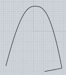
I have created 2 straight curves. Offset them vertically and horizontally, then blended with a G1 and joined them. This is what the attached file has.

But the hell, I can't get an equidistant curve of it. I thought that offset would do it, but it just won't work.

My ultimate goal is to have a solid of that shape, and, by creating equidistant lines, to boolean it out off a cube.

Any idea ?

Thanks,
Ditto
Attachments:

  Reply Reply More Options
Post Options
Reply as PM Reply as PM
Print Print
Mark as unread Mark as unread
Relationship Relationship
IP Logged

Previous
Next
 From:  Michael Gibson
4343.2 In reply to 4343.1 
Hi Ditto - yes usually you want to use the Offset command to create a curve that is a constant thickness away from an existing one.

Over here when I use the Offset command on your curve, it seems to work fine... But note that your curve is a planar curve in the Front view - that means that to use Offset you will need to pick a point in that Front view to produce the offset.

My guess is that you were possibly trying to go to the Top view to produce the offset? Going to the Top view will not produce any result with Offset, because Offset is going to try to produce an offset curve within the same plane as the existing curve, and when you go the Top view that is looking directly down at the edge of that plane.

Just to illustrate more, Offset will produce results like this (seen here in the Front view):


I suspect that what you may want is actually just a copy of the curve, positioned at a certain distance away from it in the Top view, instead of the kind of result that Offset makes? If so to do that, select the curve and run the Transform > Copy command. Pick the base point somewhere (doesn't actually matter exactly where, but somewhere on the curve is convenient), and then for the target point of the copy if you want to place it a specific distance away enter that distance value to activate "distance constraint" and then the copy will use that specific displacement from the base point.

Like for instance if you want to make a copy exactly 5 units away, select the curve, run the Transform > Copy command, click the base point on the curve, then type in 5 and push enter to activate distance constraint, now when you move the mouse to place your target point you will be picking a displacement of 5 units for placing the copy.

When picking the second point to be copied, make sure "Straight Snap" is enabled if you want to place the copy displaced along an axis direction - when straight snap is enabled you will get directional snaps along the x and y axis in any command that picks 2 points in sequence like Copy or drawing lines, etc...

Please let me know if the Copy command does not do what you need or if you're still stuck.

- Michael
Attachments:

  Reply Reply More Options
Post Options
Reply as PM Reply as PM
Print Print
Mark as unread Mark as unread
Relationship Relationship
IP Logged

Previous
Next
 From:  Michael Gibson
4343.3 In reply to 4343.1 
Also if you need to produce multiple copies in a single direction the Transform > Array > Dir command is good for doing that.

- Michael
  Reply Reply More Options
Post Options
Reply as PM Reply as PM
Print Print
Mark as unread Mark as unread
Relationship Relationship
IP Logged

Previous
Next
 From:  BurrMan
4343.4 In reply to 4343.3 
You can even create those solids with the offset command!!! Select your curve then run the offset command, select "both sides" and "Cap ends". Then extrude the new result for your solid.. Do this in the fron view as Michael points out.
  Reply Reply More Options
Post Options
Reply as PM Reply as PM
Print Print
Mark as unread Mark as unread
Relationship Relationship
IP Logged

Previous
Next
 From:  Ditto
4343.5 In reply to 4343.2 
Hi Michael, and many thanks for your quick reply.

I have had some different results during my trials to get this done. And I have always been in Front view.

I have had those that you show in your screenshot : It seems that on one side of the "break", the blend is more like a G0, ie. very hard. And certainly not like the G1 and the bulge that I have originally created.

Then I have had another result that is some sort of self-inflection. This is shown in the attached file. Which is, just to be clear, the same file I have uploaded earlier plus an offset command of 1. So your offset result is very different from mine, it seems.

If you will, let's not waste energy on this. For me it is just an exercise, and I will find a way. No problem.

Thanks anyway, really,
Ditto
Attachments:

  Reply Reply More Options
Post Options
Reply as PM Reply as PM
Print Print
Mark as unread Mark as unread
Relationship Relationship
IP Logged

Previous
Next
 From:  Michael Gibson
4343.6 In reply to 4343.5 
Hi Ditto,

> I have had those that you show in your screenshot : It seems
> that on one side of the "break", the blend is more like a G0, ie.
> very hard. And certainly not like the G1 and the bulge that I have
> originally created.

Yes, but that's the correct result of creating something that is a constant distance away from the original.

You're running into the situation where you have a tight bend in your curve and where you are asking for an offset distance that is greater than the radius of the bend itself.

In such situations you will get a sharp corner where the different sides around the tight bend hit each other.

Here's an illustration of what physically happens when you have a length that is longer than the radius of the bend that it is going around:
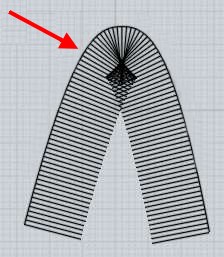

So basically an offset curve is creating a curve like the end of that line that you see being stepped around the curve there - if you cut out the messy area, note that you'll get a result with a sharp point in it like this (red traced areas) :


It's not physically/geometrically possible to have an output curve in that situation that is simultaneously 1 unit away from your source curve while also being smooth - if you want a smooth curve then that means you would not have a true constant thickness offset. So you kind of have to decide which of those properties is most important to you - the combination of both properties simultaneously (smoothness + constant distance) is not physically possible with that source shape and with that offset distance.


> Then I have had another result that is some sort of
> self-inflection. This is shown in the attached file. Which
> is, just to be clear, the same file I have uploaded earlier
> plus an offset command of 1. So your offset result is very
> different from mine, it seems.

Did you possibly uncheck the "Trim" option here?


When that Trim checkbox option is off, that is normal to get output like the file you attached - it basically gives you the raw offset result without any attempt to remove the collapsed areas. Sometimes with more complex outlines the removal code may end up removing more or different parts of the result than what you want, so that option is included so you can get the raw results in cases like that and do manual trimming for cleaning it up.

- Michael

  Reply Reply More Options
Post Options
Reply as PM Reply as PM
Print Print
Mark as unread Mark as unread
Relationship Relationship
IP Logged

Previous
 From:  Michael Gibson
4343.7 In reply to 4343.5 
Hi Ditto, also another way to describe it if it helps -

This sharp point here that you don't like:


That point is a constant distance away from the original curve - the way that distance is measured is from that point to the closest location on the curve which will be along perpendicular lines to the curve like this:


Now imagine if there was some rounding happening at that corner instead of it being sharp - the rounded area would be further away from the curve than your offset distance, and so would not be a true constant-distance offset result any longer:


Offset is focused on generating a constant distance result, so that's why it will produce those sharp corners in situations like this - otherwise if it rounded those off automatically it would not be producing an actual offset curve.

But you can round those corners off by some other operations after the offset if that's the result you want - one convenient way is to use the Fillet command which can fillet corners of a curve like that and put in an arc piece in there.

- Michael

  Reply Reply More Options
Post Options
Reply as PM Reply as PM
Print Print
Mark as unread Mark as unread
Relationship Relationship
IP Logged
 

Reply to All Reply to All