trim/boolean/extrude command with curves

Next
 From:  BurrMan
4228.1 
Michael, this may sound odd for some situations but I was trying to think of this working..

Having the trim and boolean/extrusion commands work in the same manner as sweep, with regard to the ability to create curves outside of the bounds or actual placement of the profile..

It seems like it could create a nice workflow (as opposed to really adding anything you cant already do now)

So like if you need to cut 3 .5 holes, instead of drawing the 3 holes and doing the boolean diff, you could just select 1 hole drawn off to the side, then perform the boolean diff by defining the placment with some picks.. (Direction would come from viewport) This could work with various extrusions and stuff also..

Is this command workflow available to the boolean/trim/extrusion with 2d curves?
  Reply Reply More Options
Post Options
Reply as PM Reply as PM
Print Print
Mark as unread Mark as unread
Relationship Relationship
IP Logged

Previous
Next
 From:  Michael Gibson
4228.2 In reply to 4228.1 
Hi Burr, well one of the reasons there is that "auto place" mode for sweep where you can draw stuff off to the side and flat on the plane is because it can be inconvenient to create stuff directly in place on the rail if the rail is just freely bending around in space.

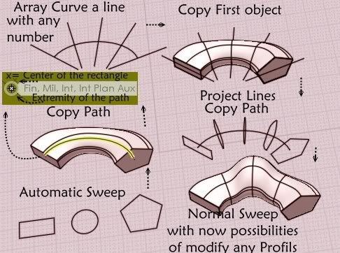
Here's an example - you can take these curves drawn flat on the plane:


Then when doing a sweep the "auto place" mode will automatically move and rotate those curves into different stations along that curve, to make this result:


So that's performing some movement and rotation steps that would be kind of inconvenient to do manually.


But from what you are describing where the boolean direction would come from the viewport, it is not very difficult to make the curve copies for that case - you can use the Transform > Copy command to place several with clicks, or use the array tools to make some kind of pattern arrangement.

So because it's not so difficult to get curves arranged in just a 2D pattern, having some kind of custom step in booleans to do something like that would not really be delivering a whole lot that you couldn't already get done easily. The downside to adding a lot of extra special case stuff to any particular command is that it increases the complexity of the command, just incrementally making things more difficult to use...

One thing that I do want to add to booleans though is an option to limit the depth of the automatic extruded shapes so that you could specify how deep the hole should be instead of it only going all the way through the object... I think this would have some good potential to save a lot of manual steps for making indentations onto curved surfaces which can take several steps to do right now.

But it's a bit harder to justify adding in some special function to the booleans if you can already get the same job done with about the same number of clicks using existing tools - so like for example with an "auto place" boolean that used the view direction just using the Transform > Copy command to copy your cutting curve first before doing the boolean gives you that same kind of a thing...

- Michael

  Reply Reply More Options
Post Options
Reply as PM Reply as PM
Print Print
Mark as unread Mark as unread
Relationship Relationship
IP Logged

Previous
Next
 From:  Michael Gibson
4228.3 In reply to 4228.1 
Hi Burr, so basically what it comes down to is that there is also some value in each command being simple and easy to use...

A lot of nested options within commands can tend to bring complexity into the command as well, so options kind of have to "pull their weight" - they kind of need to deliver something more convenient than just replacing using the Transform > Copy command for example...

One thing that would kind of fit the workflow that you are describing would be if you could copy a logical "feature" - that would be something like select the hole and then use the Copy command and have it actually copy the hole to new spots to make new holes rather than just replicating raw geometry. There are some direct modelers that can work like this, like SpaceClaim. It requires quite a lot of fairly difficult stuff to implement though, stuff like feature recognition and maybe some more complexity in how to do selections. So that's probably not in the cards for MoI anytime too soon.

- Michael
  Reply Reply More Options
Post Options
Reply as PM Reply as PM
Print Print
Mark as unread Mark as unread
Relationship Relationship
IP Logged

Previous
Next
 From:  Frenchy Pilou (PILOU)
4228.4 
< a sweep the "auto place"
In this mode profils generator equally generated are not visible in the result
(their positions)
Is that normal?

EDITED: 28 Apr 2011 by PILOU

  Reply Reply More Options
Post Options
Reply as PM Reply as PM
Print Print
Mark as unread Mark as unread
Relationship Relationship
IP Logged

Previous
Next
 From:  Michael Gibson
4228.5 In reply to 4228.4 
Hi Pilou,

> In this mode profils generator equally generated are not
> visible in the result
> Is that normal?

The profiles are what define the shape of the result, so they are visible in the sense that you can see the resulting sweep surface that was created using the profile...

It is normal that there are not extra curve objects created in the result - that's because the sweep command is focused on building surfaces, not on creating curves.

I suppose it could have been possible to temporarily draw the positioned curves and have those go away when the command ended, but I'm not sure why that would be useful? It can actually be nice when you don't have too much stuff drawing on top of each other when it is not needed.

- Michael
  Reply Reply More Options
Post Options
Reply as PM Reply as PM
Print Print
Mark as unread Mark as unread
Relationship Relationship
IP Logged

Previous
Next
 From:  Frenchy Pilou (PILOU)
4228.6 In reply to 4228.5 
< but I'm not sure why that would be useful?
say you draw a hull

you draw some stations in top view without special spacing
launch the automatic sweep
So the stations are equally positionned

then you can move or transform each station profil in the result if needing ;)
And re-use them in a normal sweep

(move horizontally a profil between 2 others are no effect in the automatic sweep mode)

EDITED: 28 Apr 2011 by PILOU

  Reply Reply More Options
Post Options
Reply as PM Reply as PM
Print Print
Mark as unread Mark as unread
Relationship Relationship
IP Logged

Previous
Next
 From:  Michael Gibson
4228.7 In reply to 4228.6 
Hi Pilou, positioning just curves in that way would probably be better suited for some other command that was focused on doing just transformations of curves and not the sweep command. The sweep command is focused on constructing a surface.

- Michael
  Reply Reply More Options
Post Options
Reply as PM Reply as PM
Print Print
Mark as unread Mark as unread
Relationship Relationship
IP Logged

Previous
Next
 From:  Frenchy Pilou (PILOU)
4228.8 In reply to 4228.7 
Of course i can extract a profil by some function
from the result of the automatic sweep but I must search the position :)
  Reply Reply More Options
Post Options
Reply as PM Reply as PM
Print Print
Mark as unread Mark as unread
Relationship Relationship
IP Logged

Previous
Next
 From:  Michael Gibson
4228.9 In reply to 4228.8 
Hi Pilou, you can also use the Transform > Orient command to position a flat curve on to a rail curve like this:


That's probably the way to go since for the purpose you were describing you wanted to tweak the location of the curve to some custom position instead of the halfway point of the curve which the regular sweep already makes for you?

- Michael
Attachments:

  Reply Reply More Options
Post Options
Reply as PM Reply as PM
Print Print
Mark as unread Mark as unread
Relationship Relationship
IP Logged

Previous
Next
 From:  Frenchy Pilou (PILOU)
4228.10 In reply to 4228.9 
Yes I can but when you have 20 sections it's not the same ;)
And I don't know where is the middle of the path ;)

So maybe a possible way
The only thing is exist a very very little glitch

In one word: centers of the rectangle & Polygon are not
the extremity of the path after the automatic sweep!

Perfect except the very little problem at the extemities!
(visible as bold lines on end "rectangle' & "polygon")

EDITED: 29 Apr 2011 by PILOU

  Reply Reply More Options
Post Options
Reply as PM Reply as PM
Print Print
Mark as unread Mark as unread
Relationship Relationship
IP Logged

Previous
Next
 From:  ed (EDDYF)
4228.11 In reply to 4228.2 
"One thing that I do want to add to booleans though is an option to limit the depth of the automatic extruded shapes so that you could specify how deep the hole should be instead of it only going all the way through the object... I think this would have some good potential to save a lot of manual steps for making indentations onto curved surfaces which can take several steps to do right now."

That would be very useful.

Ed
  Reply Reply More Options
Post Options
Reply as PM Reply as PM
Print Print
Mark as unread Mark as unread
Relationship Relationship
IP Logged

Previous
Next
 From:  BurrMan
4228.12 In reply to 4228.11 
Thanks Michael,
The "Carry their weight" part helps me with future suggestions.
  Reply Reply More Options
Post Options
Reply as PM Reply as PM
Print Print
Mark as unread Mark as unread
Relationship Relationship
IP Logged

Previous
Next
 From:  Michael Gibson
4228.13 In reply to 4228.10 
Hi Pilou,

> And I don't know where is the middle of the path ;)

Well if you want it to be placed in the middle of the path the default sweep will do that - for the situation you were talking about it sounded like you wanted to move it to somewhere else other than the middle of the path. If you wanted to move it somewhere else other than the middle, then why do you care where the middle is?

You can find the middle of the path by placing a point object at the start of it and doing an array curve to duplicate it at evenly spaced points along it.


> In one word: centers of the rectangle & Polygon are not
> the extremity of the path after the automatic sweep!

They actually are - you may see a little tiny bit of solid looking curve poking out from them, but that is just a display artifact. Part of the process of drawing curves is that they are pulled forward a little bit in depth so that a curve that is on a surface like an edge or something does not get drawn partially submerged in the surface. That little bit that you see at the end is just a side effect of that pulling forward mechanism.

The realtime display has to make various compromises in order to be fast, so it's not generally possible to get pixel perfect results with it. You just need to ignore some small little display glitches like that.

- Michael
  Reply Reply More Options
Post Options
Reply as PM Reply as PM
Print Print
Mark as unread Mark as unread
Relationship Relationship
IP Logged

Previous
Next
 From:  Frenchy Pilou (PILOU)
4228.14 In reply to 4228.13 
< looking curve poking out from them, but that is just a display artifact.
< They actually are

If after the automatic Sweep I make a zoom the "end" (snap point of the path) and middle of the rectangle writed "Center" are different.
Shown by my little green part image above (the x of the "center" was very blury)
Do you mean they are same? If yes that is perfect for me! Very cool! :)
I will made my line array curve from the end of path and not from the center of rectangle for more security


< then why do you care where the middle is?
for start to move from a known position
But with your last comment there is no more problem, i take just an odd array curve and I have the middle ;)

EDITED: 29 Apr 2011 by PILOU

  Reply Reply More Options
Post Options
Reply as PM Reply as PM
Print Print
Mark as unread Mark as unread
Relationship Relationship
IP Logged

Previous
Next
 From:  Michael Gibson
4228.15 In reply to 4228.14 
Hi Pilou,

> If after the automatic Sweep I make a zoom the "end"
> (snap point of the path) and middle of the rectangle
> writed "Center" are different.

It looks like in your example you don't have a simple only 4-sided rectangle at the end of your sweep because you're morphing from a rectangle to a pentagon in the sweep, so that causes some of the resulting edges to be made up of various segments instead of just 4 sides.

The center snap will not be very meaningful on that kind of multi-segmented result face, the way center snap works on a face is if the face is bounded by line segments it takes the centroid of those line segments for the center snap. It's not very meaningful on a multi-segmented result with some small lines mixed in with longer lines like you've got there, you should just ignore the center snap in your particular case with that odd geometry.


> for start to move from a known position

If that known position is not the position you want, then why do you care where it is?

At any rate, place a point object and then use Array curve to replicate it the point (use item count = 3) to position a point object at the middle point of the curve. That will allow you to snap on to that location.

- Michael
  Reply Reply More Options
Post Options
Reply as PM Reply as PM
Print Print
Mark as unread Mark as unread
Relationship Relationship
IP Logged

Previous
Next
 From:  Frenchy Pilou (PILOU)
4228.16 In reply to 4228.15 
< you don't have a simple only 4-sided rectangle
is that i had remarked my rectangle was multi segmented but thinking that had no incidence of its center!

<If that known position is not the position you want, then why do you care where it is?
it's alway good to know the middle of something ;)

< The center snap will not be very meaningful
I was affraid because i had made my array curve from the center and not from the end of the path so result was significant at the extremities for some function
Now I will take the end of path :)
Thx for the help and explanation!

Line both sides + array cuve line + Project lines are very funny for obtain numerous profils without effort from any volum!
  Reply Reply More Options
Post Options
Reply as PM Reply as PM
Print Print
Mark as unread Mark as unread
Relationship Relationship
IP Logged

Previous
Next
 From:  ed17 (ED17ES)
4228.17 
Talking about mixing commands, I think you could merge the plane and network commands to just one button, that new command could identify the result you expect based on the selection. Just a suggestion.
  Reply Reply More Options
Post Options
Reply as PM Reply as PM
Print Print
Mark as unread Mark as unread
Relationship Relationship
IP Logged

Previous
Next
 From:  Michael Gibson
4228.18 In reply to 4228.17 
Hi ed,

> I think you could merge the plane and network commands
> to just one button, that new command could identify the result
> you expect based on the selection. Just a suggestion.

Possibly... But actually those 2 commands will currently produce slightly different output when given some of the same kinds of inputs. Like if you have a 4-sided boundary like this:


The Planar command will build a trimmed plane surface for that, while Network will make an untrimmed surface. You'll see the difference if you turn on surface control points for each of those results.

Also the Planar command actually does already have some multi use built into it currently - you can also use it to fill in planar openings on a surface object in addition to building a trimmed plane through a planar set of curves.

In the future I have to figure out where to put another kind of surfacing command called "N-sided patch", and I've been trying to think of how it might be combined with one of these as well.

But it can be a bit tricky to combine things when there are 2 different results possible from the same inputs...

- Michael
Attachments:

  Reply Reply More Options
Post Options
Reply as PM Reply as PM
Print Print
Mark as unread Mark as unread
Relationship Relationship
IP Logged

Previous
 From:  ed17 (ED17ES)
4228.19 
I understand, and i like the work youve done so far, then keep going!
  Reply Reply More Options
Post Options
Reply as PM Reply as PM
Print Print
Mark as unread Mark as unread
Relationship Relationship
IP Logged
 

Reply to All Reply to All