About Hulls
 1-20  21

Next
 From:  Frenchy Pilou (PILOU)
4222.1 
What is your best methods?

ABC = face with 3 "sides"
BCDE = face with 4 "sides"

ED, BC, AC must have same number of segments (control points) ?

For the surfaces : Sweep, Network, Lineweb(then some networks), Loft ...?
Surface by surface then join it?

If I want some thickness what is your best tricks?
Shell or sweep a profile, boolean Diff 2 volumes ...

Thanks by advance for your advices :)
I took the image's plans from here: Seegull by Alfred Mylne 1903
http://15marins.blogspot.com/2008/07/seagull.html

EDITED: 25 Apr 2011 by PILOU

  Reply Reply More Options
Post Options
Reply as PM Reply as PM
Print Print
Mark as unread Mark as unread
Relationship Relationship
IP Logged

Previous
Next
 From:  d^^b (DAVID)
4222.2 In reply to 4222.1 
In my last try to draw a decent hull, after draw the curves of the profiles, I rebuild them with the same number of control points.

Then, I made a loft with all of them, with "loose" option. I tried to avoid this option, but there was any area very taut.

In other cases, when the transitions of the profiles are sharp, I draw curves between them (or I copy and move the control points) in order to made the transition of the surfaces lighter.

My laptop was broken, and now I use MoI in the laptop of my wife. Later, I'll upload my last hull. ;-)

EDITED: 1 May 2011 by DAVID

  Reply Reply More Options
Post Options
Reply as PM Reply as PM
Print Print
Mark as unread Mark as unread
Relationship Relationship
IP Logged

Previous
Next
 From:  Frenchy Pilou (PILOU)
4222.3 In reply to 4222.2 
Thx for these first advices
I believe that some trainings are necessary for this sort of sport :)

first try :)
Network

  Reply Reply More Options
Post Options
Reply as PM Reply as PM
Print Print
Mark as unread Mark as unread
Relationship Relationship
IP Logged

Previous
Next
 From:  BurrMan
4222.4 In reply to 4222.3 
A note would be that ship hulls are built with waterlines and not stations. The stations are used to determine the waterlines.
  Reply Reply More Options
Post Options
Reply as PM Reply as PM
Print Print
Mark as unread Mark as unread
Relationship Relationship
IP Logged

Previous
Next
 From:  Frenchy Pilou (PILOU)
4222.5 In reply to 4222.4 
"Stations" are these vertical forms?

EDITED: 25 Apr 2011 by PILOU

  Reply Reply More Options
Post Options
Reply as PM Reply as PM
Print Print
Mark as unread Mark as unread
Relationship Relationship
IP Logged

Previous
Next
 From:  Frenchy Pilou (PILOU)
4222.6 
DIfficulty is that the "Control points" are not always the points on the curves lines
So cross curves between them or attach them are no evident :)
  Reply Reply More Options
Post Options
Reply as PM Reply as PM
Print Print
Mark as unread Mark as unread
Relationship Relationship
IP Logged

Previous
Next
 From:  BurrMan
4222.7 In reply to 4222.6 
Yes Frenchy, the stations are the contours that go from side to side and the waterlines run from front to back (Bow to stern).

You could create a plane array in the Z direction at some type of level and then the isect command from the planes and station curves would create points..
  Reply Reply More Options
Post Options
Reply as PM Reply as PM
Print Print
Mark as unread Mark as unread
Relationship Relationship
IP Logged

Previous
Next
 From:  d^^b (DAVID)
4222.8 In reply to 4222.3 
It´s ver good try. Maybe a few bumps.
I usually avoid that using loose options (I know it´s not the good way)

Well. It has been a hard week, but I send you my last hull, if you want to see.
As I told you, I have draw the curves, after I have rebuild them with the same number of points, and finally I have created the surface using Loft command.

Bye!
David
Attachments:

  Reply Reply More Options
Post Options
Reply as PM Reply as PM
Print Print
Mark as unread Mark as unread
Relationship Relationship
IP Logged

Previous
Next
 From:  d^^b (DAVID)
4222.9 
Another thing.
I extend the curves of the profiles on the top area, and then I get a surface larger that I can trim.
I has been bad explained.... :-)
Something like that
Image Attachments:
Size: 671.6 KB, Downloaded: 173 times, Dimensions: 800x600px
  Reply Reply More Options
Post Options
Reply as PM Reply as PM
Print Print
Mark as unread Mark as unread
Relationship Relationship
IP Logged

Previous
Next
 From:  Frenchy Pilou (PILOU)
4222.10 In reply to 4222.9 
Oh very cool try!
I remark the trick of the vanish points for have the good curvature at the end of the curve
Thx for the advices!
Modelisation by David!
  Reply Reply More Options
Post Options
Reply as PM Reply as PM
Print Print
Mark as unread Mark as unread
Relationship Relationship
IP Logged

Previous
Next
 From:  Frenchy Pilou (PILOU)
4222.11 
Ps
@ David about the Pilou hull :)
As your back ground images are not with the file, (just empty frames :)
have you a grab screen for see the organisation of them?
for see what are the "straight lines" floating around on top view

And do you make some clean or trim before use images?

After a Rebuild, do you move theses "control points" for have a more fluent curve between other curves rebuilded?

What will be your strategy if thickness must necessary?
Shell? Sweep profil?...
And thx again for your enlight test!

EDITED: 30 Apr 2011 by PILOU

  Reply Reply More Options
Post Options
Reply as PM Reply as PM
Print Print
Mark as unread Mark as unread
Relationship Relationship
IP Logged

Previous
Next
 From:  d^^b (DAVID)
4222.12 
Sorry. I copied the file from the backup and I forgot to copy the images :-)
Here are they

"And do you make some clean or trim before use images?"

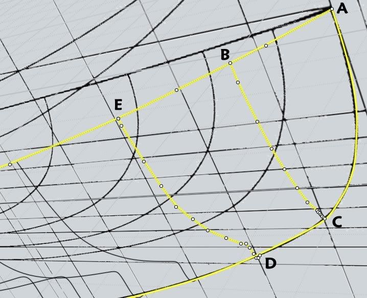
Do you mean if I manipulate the images in order to get a better layout for work? In this case I have trim the front view, only for show the hull. The upper part I'll put when I finnish the hull (any century) :-P

"After a Rebuild, do you move theses "control points" for have a more fluent curve between other curves rebuilded?"

I think that in this moment must to appear the skill of the modeler, but always, when I've tried to make that, I ruined the result.:-)
But yes, I try to move the control points in order to avoid to make a taut surface

"What will be your strategy if thickness must necessary?
Shell? Sweep profil?..."

Shell...and...I cross my fingers! :-)
Sometimes, I have tried (if shell doesn't work) a offset, and then I have made the surface between them with Sweep + 2 rails (the borders of the surfaces). But I think that it is not the good way, and it is very tedious!

Sorry if I can't help more. I think I'm not a good example.
Maybe if Mark Brown read us, he'll give us a good tips for get good results! ;-)

p.s. I'll go away for 3 days...read us then!
Image Attachments:
Size: 323.5 KB, Downloaded: 72 times, Dimensions: 3109x955px
Size: 493.9 KB, Downloaded: 52 times, Dimensions: 4292x1164px
  Reply Reply More Options
Post Options
Reply as PM Reply as PM
Print Print
Mark as unread Mark as unread
Relationship Relationship
IP Logged

Previous
Next
 From:  Frenchy Pilou (PILOU)
4222.13 In reply to 4222.12 
@ David
Do you see the water lines at the end for see if all is cool managed?
---
Pilou
Is beautiful that please without concept!
My Gallery
  Reply Reply More Options
Post Options
Reply as PM Reply as PM
Print Print
Mark as unread Mark as unread
Relationship Relationship
IP Logged

Previous
Next
 From:  BurrMan
4222.14 In reply to 4222.12 
"""""""""Sorry. I copied the file from the backup and I forgot to copy the images :-)
Here are they""""""""""

FYI: In the image dialogue there is a "properties" button and in there is an option to "embed the images" into the 3dm file...
  Reply Reply More Options
Post Options
Reply as PM Reply as PM
Print Print
Mark as unread Mark as unread
Relationship Relationship
IP Logged

Previous
Next
 From:  Frenchy Pilou (PILOU)
4222.15 

EDITED: 3 May 2011 by PILOU

  Reply Reply More Options
Post Options
Reply as PM Reply as PM
Print Print
Mark as unread Mark as unread
Relationship Relationship
IP Logged

Previous
Next
 From:  JPBWEB
4222.16 
Indeed, as a contributor to that earlier thread, I can only repeat that lofting ship hulls (and I guess many other things) works better when you use only the absolute minimum number of curves necessary to describe the surface. And it helps if the curves are 'clean' (i.e; rebuilt with even-spaced control points etc.). Also, do not attempt too much. There are features on ship hills like sonars, bulbous bows, propeller shaft housings etc. that are best added as separate pieces and blended into the simple hull.

Difficult areas in ship hulls are at the bow and stern of the ship. In such cases, blends work better and provide more suitable surfaces. But in every case, what looks like a rather simple shape turns into a rather complex thing to model. NURBS work best for non-organic shapes, but unfortunately, ship hulls are rather semi-organic shapes.
  Reply Reply More Options
Post Options
Reply as PM Reply as PM
Print Print
Mark as unread Mark as unread
Relationship Relationship
IP Logged

Previous
Next
 From:  Frenchy Pilou (PILOU)
4222.17 In reply to 4222.16 
Thx!
See my last little video (in French)
but you can see an interesting method for help the drawing of Hull
with a very cool plug by Michael ;)
Moveslicetopoint : http://moi3d.com/forum/messages.php?webtag=MOI&msg=2749.36

Video : http://moiscript.weebly.com/deacuteplacer-des-objets.html


  Reply Reply More Options
Post Options
Reply as PM Reply as PM
Print Print
Mark as unread Mark as unread
Relationship Relationship
IP Logged

Previous
Next
 From:  SteveMacc (STEVEH)
4222.18 
One of the problems with modern hulls is that they often have soft chines that don't extend right down the hull. You see them particularly at the bow and stern. Blending these is difficult.
  Reply Reply More Options
Post Options
Reply as PM Reply as PM
Print Print
Mark as unread Mark as unread
Relationship Relationship
IP Logged

Previous
Next
 From:  d^^b (DAVID)
4222.19 In reply to 4222.14 
Hi Burrman:

Thank you for the info. I was thinking it would be a good idea to let a picture embebded in a 3dm file and.....MoI always go a lot of step ahead me :-)

Pilou:

Your video are very interesting, but...when you draw the upper curve of the bow, I think that could be better if you extend the curves of the deck or the upper area of the hull, and then you build the curve of bow on it.
Like that:

EDITED: 10 May 2011 by DAVID

Image Attachments:
Size: 27 KB, Downloaded: 30 times, Dimensions: 600x408px
Size: 27.7 KB, Downloaded: 23 times, Dimensions: 600x408px
Size: 37.1 KB, Downloaded: 25 times, Dimensions: 600x358px
Size: 29.3 KB, Downloaded: 23 times, Dimensions: 600x407px
Size: 37.8 KB, Downloaded: 22 times, Dimensions: 600x341px
Size: 38.7 KB, Downloaded: 27 times, Dimensions: 600x343px
Size: 42.8 KB, Downloaded: 41 times, Dimensions: 600x361px
  Reply Reply More Options
Post Options
Reply as PM Reply as PM
Print Print
Mark as unread Mark as unread
Relationship Relationship
IP Logged

Previous
Next
 From:  Frenchy Pilou (PILOU)
4222.20 In reply to 4222.19 
Thx!

Yes it was just for show some other tools ;)

You can also make a simple Blend : advantage you can regulate visually the intensity of the curvature with a cursor!
(input values inside the box dialog can be increase with big amplitude :)

EDITED: 10 May 2011 by PILOU

  Reply Reply More Options
Post Options
Reply as PM Reply as PM
Print Print
Mark as unread Mark as unread
Relationship Relationship
IP Logged
 

Reply to All Reply to All


Show messages:  1-20  21