2CV

Next
 From:  Rudl
3981.1 
I am making the tutorial of lyes. http://vimeo.com/17694097

In minute 1:59 I cannot make the fillet, and in minute 2:41 I cannot make the blend.

I have attached the images and .3dm file.

Rudl

PS: I still have a 2CV in my barn, if some has interest, it is for free. Maybe, it is 40 years old.
Attachments:

  Reply Reply More Options
Post Options
Reply as PM Reply as PM
Print Print
Mark as unread Mark as unread
Relationship Relationship
IP Logged

Previous
Next
 From:  Michael Gibson
3981.2 In reply to 3981.1 
Hi Rudl - for the blend part you need to select edge objects to do the blend. But in your model you have some separate construction curves that are exactly overlapping over top of the surface edges and those can make it difficult to select edges.

So you need to delete or hide those curve objects so that you can more easily select the surface edges instead.

To do that select these 2 curves:


And then either hide or delete those to get them out of the way.

After you do that it will then be easier to select the surface edges which are in those same locations. To select the edges you will click first on the surface that owns the edge and then do a second click on the edge to switch the selection to it.

Once you have the 2 surface edges selected instead of those 2 separate original generator curves selected, then you should find that Blend will work as you were expecting.

In general it's a good idea to either hide or delete construction curves that are right on top of a generated surface after the surface has been created to get the original curves out of the way.

- Michael
Attachments:

  Reply Reply More Options
Post Options
Reply as PM Reply as PM
Print Print
Mark as unread Mark as unread
Relationship Relationship
IP Logged

Previous
Next
 From:  Rudl
3981.3 In reply to 3981.2 
Thank you,

it seems I have understand an imported thing. When I did a surface I have the surface with it´s own edges and also the original edges. Is this right?

Rudl
  Reply Reply More Options
Post Options
Reply as PM Reply as PM
Print Print
Mark as unread Mark as unread
Relationship Relationship
IP Logged

Previous
Next
 From:  Rudl
3981.4 In reply to 3981.3 
What is with the fillets. I thought this is the same problem, but it´s seems to be another problem.

Rudl
  Reply Reply More Options
Post Options
Reply as PM Reply as PM
Print Print
Mark as unread Mark as unread
Relationship Relationship
IP Logged

Previous
Next
 From:  Michael Gibson
3981.5 In reply to 3981.1 
Hi Rudl - re: fillet your side surfaces are kind of a bit lumpy and have a kind of tight bend in a very small area right near the corner here:


If I turn on reflective metallic style lighting (under Options > View > Lighting options), and zoom in a ways on that corner you can see the shaded areas which indicate that there is some tight curvature nearby there:


That kind of bunching and tight curvature in a small area is a kind of bad quality surface and filleting is pretty sensitive to such things.

It's fairly easy to get bad surface quality like that when surfaces have areas that are collapsing together, which is what happens if you build a 3 sided surface as in this case.

If you separate that surface out to be an individual surface and turn on its surface control points, you'll see they look like this:


So notice there that all the control points are kind of collapsing down to a sort of "pole" area and bunching together in lines like this:


That kind of bunching is good to avoid if possible, it is just too easy for there to be irregularities and things like little lumps and bumps in those collapsed zones.

lyess' version just happened to be proportioned evenly enough to avoid quite as bad of problems in that area.

Instead of building a surface bounded by 3 curves (which by its nature forces one spot to be collapsed down), I'd instead recommend making an initial surface that has a 4-sided boundary which can then be much more regularly shaped without any bunching or bad areas in it.

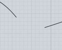
That would go something like this - here I have a profile curve and generate a sweep from it:


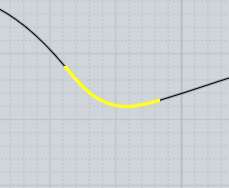
Then to produce the final outline you draw in some curves from the side view like this:


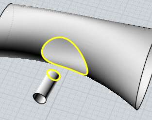
And then use it to trim the surface like this:


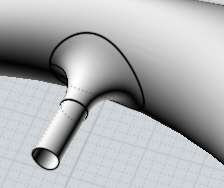
That will make 2 fragments and the top part can be deleted to leave you with this shape:


Now if I turn on surface control points for this shape notice how they are formed:


So see there how the surface control points are much more regular and not bunched together in any awkward way? That helps to make a much higher quality surface that won't have little weird folded spots in it. Surfaces like this will be handled much better by other processes such as filleting and also offsetting or shelling.

So usually it's better to build surfaces in this way by making are more regular layout to the initial surface and then trim it to get the 3-sided boundary rather than trying to construct the surface directly to a 3 sided boundary right in its initial construction.

- Michael

  Reply Reply More Options
Post Options
Reply as PM Reply as PM
Print Print
Mark as unread Mark as unread
Relationship Relationship
IP Logged

Previous
Next
 From:  Michael Gibson
3981.6 In reply to 3981.4 
Hi Rudl,

> What is with the fillets. I thought this is the same
> problem, but it´s seems to be another problem.

Sorry I should have mentioned that I was preparing a second post to answer the part about the fillet problem - that answer is above now.

- Michael
  Reply Reply More Options
Post Options
Reply as PM Reply as PM
Print Print
Mark as unread Mark as unread
Relationship Relationship
IP Logged

Previous
Next
 From:  Michael Gibson
3981.7 In reply to 3981.3 
Hi Rudl,

> it seems I have understand an imported thing. When I
> did a surface I have the surface with it´s own edges
> and also the original edges. Is this right?

Yes, that's correct. But just to be clear the name "Edge" in MoI means something different than just "Curve".

A curve is a wire-like object that you initially draw like lines or arcs or control point curves, etc...

Surfaces can be constructed from curves and each surface has a trimming boundary that defines which part of the surface is active and which parts are holes within the surface area.

Those trimming boundaries are made up of "Edge" objects. They are wire-like objects like curves (and in fact you can select them to be used by several commands as if they were a curve like you can extrude them, etc...) but the difference is that they are not a complete "top level" object all by themselves, they are actually a kind of child of the surface object.

Some commands work by selecting "edge" objects specifically, and some may give you some different results depending on whether a standalone curve object was selected or whether edges were selected.

If you have the original curve objects sitting in the exact same area as an edge, it can make it difficult to select the edge instead of the curve object. In cases like that you want to hide or delete the original curve objects so that they do not interfere with selection of the edge.

Blend for example is a command that does different things depending on whether you give it a curve selection or an edge selection.

If you select 2 curve objects, then when you do Blend it will build a blend curve result between their endpoints like this:


That is what it was trying to do in your particular case, and because you had 2 curves that did not have any empty space in between their endpoints it would have been difficult to see any result there.

If you select 2 surface edges then Blend will build a blend surface that comes away from the edge, like this instead:


- Michael
  Reply Reply More Options
Post Options
Reply as PM Reply as PM
Print Print
Mark as unread Mark as unread
Relationship Relationship
IP Logged

Previous
Next
 From:  Michael Gibson
3981.8 In reply to 3981.1 
Hi Rudl, also one way to kind of improve the model without fully rebuilding it is to make it into a solid by lofting some of the bottom pieces and joining those surfaces together, then scale it just in the x-axis direction to stretch it out a bit.

Then a new surface constructed using a sweep as I described above can be positioned like this:


And then Boolean difference can be used to cut the body with that new surface, and the outer solid pieces can be deleted, that will essentially remove the previous side surface and replace it with the new sweep one:


I've attached a 3DM model file that has that done to it, this version should fillet better now.

- Michael

  Reply Reply More Options
Post Options
Reply as PM Reply as PM
Print Print
Mark as unread Mark as unread
Relationship Relationship
IP Logged

Previous
 From:  Rudl
3981.9 In reply to 3981.8 
Thank you very much, you are great.

I will study it tomorrow, we have here now twelve o´clock.

Rudl
  Reply Reply More Options
Post Options
Reply as PM Reply as PM
Print Print
Mark as unread Mark as unread
Relationship Relationship
IP Logged
 

Reply to All Reply to All