Shell help

Next
 From:  Alexander (ALEXCAD)
3965.1 
Hello

Just a quick query regarding shelling, has anyone had this happen were a corner seems to protrude/crease outwards?
This has to be a 2mm as shown, I assume it has something to do with the radius.
Anyone know any workarounds to either prevent this or to delete the excess material afterwards?

As ever, any help appreciated.

Alexander


Attachments:

  Reply Reply More Options
Post Options
Reply as PM Reply as PM
Print Print
Mark as unread Mark as unread
Relationship Relationship
IP Logged

Previous
Next
 From:  Frenchy Pilou (PILOU)
3965.2 In reply to 3965.1 
Post your 3dm file more easy for help ;)
---
Pilou
Is beautiful that please without concept!
My Gallery
  Reply Reply More Options
Post Options
Reply as PM Reply as PM
Print Print
Mark as unread Mark as unread
Relationship Relationship
IP Logged

Previous
Next
 From:  Michael Gibson
3965.3 In reply to 3965.1 
Hi Alexander, yes can you please post the 3DM file, that would make it easier to examine what you are running into.

But part of the process of Shell involves doing an offset of surfaces and if the surfaces are not smooth where they touched it will also try to extend the offset results.

So you may be seeing the result of that extension process.

But it's a bit hard to tell just from the screenshot without seeing the actual model file - if your surface is kind of lumpy or wrinkled or folded back on top of itself, that can cause a lot of problems for shelling as well because creating a surface offset tries to make a new surface that is moved away from the original along the original's surface normal, and if the original surface normal is going kind of crazy jiggling around too much instead of nice and smooth it can make it difficult to create a good offset. Basically any folds or jiggles in the original surface tend to get magnified when creating an offset from it.

One thing you can try in cases like this is to use Edit > Separate on your model and then use Offset to create offsets of the individual surfaces. If those look wonky then you may have some kind of bad quality surface that has normal/wiggling/folding problems in it. If the individual offsets look good then you're probably running into problems around the surface extension mechanism in shell - to fix stuff like that means making a better quality initial model that has pieces that are smooth where they touch each other instead of meeting in a crease.

But in general Shell is a sensitive operation and it does not tolerate messy situations very well... So if you intend to shell a model you usually have to make the original shape to be a nice clean starting shape.

- Michael
  Reply Reply More Options
Post Options
Reply as PM Reply as PM
Print Print
Mark as unread Mark as unread
Relationship Relationship
IP Logged

Previous
Next
 From:  Michael Gibson
3965.4 In reply to 3965.1 
Hi Alexander, also another note is that if you have any tightly bent shapes in your original surface that will limit the distance that you'll be able to offset the shapes.

If you have something going around a tight bend and you ask for an offset distance that is larger than will fit, it will cause bunching to happen, here's an example:


- Michael
  Reply Reply More Options
Post Options
Reply as PM Reply as PM
Print Print
Mark as unread Mark as unread
Relationship Relationship
IP Logged

Previous
Next
 From:  SteveMacc (STEVEH)
3965.5 In reply to 3965.4 
Michael,

Is there a way with the library you use to get the shell tool to "fill in" the overlaps? Solidworks does this when you run the thicken tool. It creates the inset surface sort of following the end of the non- overlapped bits (e.g. in the example you show, SW would create the inner surface with a sharp edge at the top). SW's thicken command only fails if the thicken distance is more than the maximum space available, so there is no inner surface at all.

Here is a screen shot of what I mean. This is a revolved surface with thicken applied:

EDITED: 9 Jan 2011 by STEVEH

Image Attachments:
Size: 40.3 KB, Downloaded: 45 times, Dimensions: 550x640px
  Reply Reply More Options
Post Options
Reply as PM Reply as PM
Print Print
Mark as unread Mark as unread
Relationship Relationship
IP Logged

Previous
Next
 From:  Michael Gibson
3965.6 In reply to 3965.5 
Hi Steve,

> Is there a way with the library you use to get the shell
> tool to "fill in" the overlaps?

There is an option in the library to try and deal with a self-intersecting result, but I'm not sure how well it works. It's something I can experiment with in the future though.

One issue though is that trying to process such things can slow down the processing of the offset calculation by quite a lot, and it kind of goes about processing stuff in a different manner so I'm worried about just having that kind of processing turned on in all cases. I may need to do something like try to determine in advance in some kind of quicker way if it's going to self-intersect at the given distance before trying to handle it...

- Michael
  Reply Reply More Options
Post Options
Reply as PM Reply as PM
Print Print
Mark as unread Mark as unread
Relationship Relationship
IP Logged

Previous
Next
 From:  Alexander (ALEXCAD)
3965.7 
Hey guys,

Thanks for the feedback.
I have attached the model. I created the top profile using the extrude & trim combo and the side was created with the sweep along two rails. Then joined them and added a 2mm radius to the top. I think the corner profiles are too complex for the shell command, I did use the loft command to create the sides but got the same results.

A bit tricky this one, for me anyway being a nurbs noob :)

Cheers
Alexander
Attachments:

  Reply Reply More Options
Post Options
Reply as PM Reply as PM
Print Print
Mark as unread Mark as unread
Relationship Relationship
IP Logged

Previous
Next
 From:  Michael Gibson
3965.8 In reply to 3965.7 
Hi Alexander - so what's happening in this case is that your original surface is kind of angled in those corner areas instead of coming to a full 90 degree vertical end in those areas.

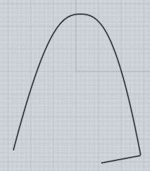
When you shell by thickening an open surface, the result follow the surface normal. So for example if you have a shape that has a side profile that looks like this:


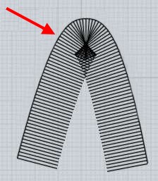
When the surfaces are offset it will go perpendicular to that, making something like this:


That's what is producing the little raised areas - the profiles in the corners are kind of stretched out. You may want to build the corners of things like this by filleting an initial blockier shape instead, instead of trying to build a long single surface that goes through a sudden bend like that.

But there is a different way that you can use Shell that I think will give you what you want - instead of trying to thicken an initially open surface, you can instead use Shell to hollow out a solid.

When you use it to hollow out a solid, it will make a result that is flush to the face that you pick to be the opening, regardless of what is happening along the side wall portions (bits of the side walls that would have been sticking up past the open face will get trimmed off).

So for your case here, you want to build a solid out of your base shape instead of having it only open surfaces. To do that, select your base surfaces here:


Then run the Construct > Planar command, that will fill in a planar cap along the top to make it into a solid, it will look like this:


Now select that planar face, you do this by a 2nd click on the object, the first click selects the whole object and then a 2nd click on it will "drill down" to select edges or faces, in this case select the face.

When you use Shell with faces selected it will hollow out the object and leave that selected face as the opening. So your selection should look like this now:


Then when you run Shell it will produce a result like you were wanting I think:


The result is attached here as top_shelled.3dm

Hope this helps!

- Michael

  Reply Reply More Options
Post Options
Reply as PM Reply as PM
Print Print
Mark as unread Mark as unread
Relationship Relationship
IP Logged

Previous
Next
 From:  Alexander (ALEXCAD)
3965.9 In reply to 3965.8 
Michael,
That's exactly the result I wanted and many thanks for the detailed explanation.

I'm really enjoying using MoI and learning new modelling techniques.

Regards
Alexander
  Reply Reply More Options
Post Options
Reply as PM Reply as PM
Print Print
Mark as unread Mark as unread
Relationship Relationship
IP Logged

Previous
Next
 From:  Alexander (ALEXCAD)
3965.10 In reply to 3965.9 
Michael,

Sorry to bother you again regarding my problem, I did exactly as you said which worked perfectly thanks. But I have had to change the profile very slightly and now it won't shell properly. It seems to take forever to calculate and then jumbles everthing up. Its driving me crazy.

Please help...

Regards
Alexander
Attachments:

  Reply Reply More Options
Post Options
Reply as PM Reply as PM
Print Print
Mark as unread Mark as unread
Relationship Relationship
IP Logged

Previous
Next
 From:  Michael Gibson
3965.11 In reply to 3965.10 
Hi Alexander,

> It seems to take forever to calculate and then jumbles everthing up.

Usually a result like that means that one of your surfaces may be bunched up and sort of folding back over top of itself in a small area.

The way shelling and offsetting work, they produce a result that follows the surface normal a distance away from the original surface.

But if your surface folds back over top of itself, that means the surface normal (the perpendicular coming off of the surface) jumps around wildly in that area, which interferes with getting a good surface offset calculated from it.

That's just some general stuff to look for, I haven't checked out your model yet but I will take a look at it now.

- Michael
  Reply Reply More Options
Post Options
Reply as PM Reply as PM
Print Print
Mark as unread Mark as unread
Relationship Relationship
IP Logged

Previous
Next
 From:  Michael Gibson
3965.12 In reply to 3965.10 
Hi Alexander, so one problem I see right off the bat with your model is that it is not a fully closed solid - it has some unjoined edges in it.

I can tell this because when I select it, the type indicator in the upper-right area of the window says it is a "Joined srf" , if it was a totally closed solid it would read "solid" there instead:


So that's one indicator that the model is not cleanly constructed - it's got some pieces that are not joined up properly.

- Michael
Attachments:

  Reply Reply More Options
Post Options
Reply as PM Reply as PM
Print Print
Mark as unread Mark as unread
Relationship Relationship
IP Logged

Previous
Next
 From:  Michael Gibson
3965.13 In reply to 3965.10 
Hi Alexander, so the problem area of your model is in this area:


If you zoom in closely to that area you can see that there are some microscopic little surface fragments there, and it appears to have some pieces stacked up right on top of each other there:


That kind of messy area will be difficult to get a clean offset from - the offsetter will actually try to offset those little micro slivery surfaces, and try to extend them and intersect them with neighboring surfaces and stuff like that.

You really want to have a more simplified and clean model structure in order to get a good shell on it.

One thing about filleting is that you usually want the pieces you are filleting to come to more of a sharp angle and then let the filleter produce the rounded shape. In this case you've tried to make the initial surfaces come be smooth to each other, but you can see that this actually makes the filleter's job harder because it makes for a little tiny sized fillet surface when it tries to smooth out that area that you made pretty close to being smooth initially.

So that's one thing to make a better model - don't make part of the surfaces come close to being smooth to one another to start with if you want to fillet them.

Then another tip for shelling is you may want to apply the fillets _after_ you do the shell instead of applying them before. When you apply them before it means that the fillet surfaces are then some more stuff that need to be processed during the shell operation as well.

So that's what I'd recommend for this model - do you have a version of it before you applied the fillet? If so then try shelling that first, and then apply the fillet after the shell.

Also to get a proper fillet you may need to not have the initial surfaces come close to being smooth to one another as you have done here.

- Michael

  Reply Reply More Options
Post Options
Reply as PM Reply as PM
Print Print
Mark as unread Mark as unread
Relationship Relationship
IP Logged

Previous
Next
 From:  Michael Gibson
3965.14 In reply to 3965.10 
Hi Alexander, I was trying to untrim and retrim your model to get rid of the fillet, but I also ran into another problem area with it as well.

This surface here folds back over top of itself right near its ends:


If I separate that surface from the others and then turn on its control points, look at this area here which seems to be bunched up:


If I zoom in on that area, it appears to be in a kind of hook formation:


This kind of surface that folds back over top of itself is particularly bad for shelling or offsetting calculations. The surface normal that the offset tries to track along slams back and forth to opposite sides in a small area there.

It looks like this surface was created as an extrusion, but that the original curve being extruded has that kind of folded over hook at the ends.

Do you happen to have the original curve that was used to create that particular surface?

You want to be careful to make sure the original curve structure that you start with are nice and clean and don't have bad formations like this. If your original curves have bad structures in them, then those will tend to get transferred to surfaces created from those curves as well.

- Michael

  Reply Reply More Options
Post Options
Reply as PM Reply as PM
Print Print
Mark as unread Mark as unread
Relationship Relationship
IP Logged

Previous
Next
 From:  Michael Gibson
3965.15 In reply to 3965.10 
Hi Alexander, so basically this model will need to be reconstructed to remove some of these problems - that extruded side piece will need to be constructed from a better initial curve so that it doesn't have those folded-over hooks at its ends.

Then once that part of the model is cleaner you may also try doing the shell first and applying the fillet after that.

- Michael
  Reply Reply More Options
Post Options
Reply as PM Reply as PM
Print Print
Mark as unread Mark as unread
Relationship Relationship
IP Logged

Previous
Next
 From:  Alexander (ALEXCAD)
3965.16 In reply to 3965.15 
Michael, many thanks for your feedback.
I will have another go at re-modelling the part tomorrow.
Just out of interest could I create the same geometry with a different technique. The sides are rail sweeps and the top is an extrusion trimmed. I suspect there is an easier way to create the same part?

Thanks again Michael.
Alexander
  Reply Reply More Options
Post Options
Reply as PM Reply as PM
Print Print
Mark as unread Mark as unread
Relationship Relationship
IP Logged

Previous
 From:  Michael Gibson
3965.17 In reply to 3965.16 
Hi Alexander,

> I suspect there is an easier way to create the same part?

Well normally you want to try and let Fillet create the rounded corners, instead of trying to model the corners directly into your starting surfaces as you've done.

Check out these previous threads for some examples:
http://moi3d.com/forum/index.php?webtag=MOI&msg=1002.1
http://moi3d.com/forum/index.php?webtag=MOI&msg=3137.1

You can use Sweep to build chunks of the model, but normally it's better if each surface gives only one element to the final shape, like one broad surface patch and doesn't have any tight bends in it - the sweep going through a tight bend is usually an indication that you're trying to combine more than one underlying form into a single surface instead of building them separately and then filleting them where they join.

Here's another example of that kind of thing of building some broader sheets of a model out of sweeps and then having a fillet provide a smooth juncture between them:
http://moi3d.com/forum/index.php?webtag=MOI&msg=2164.2
http://moi3d.com/forum/index.php?webtag=MOI&msg=2164.4

It tends to be hard to control things when you try to do too much of the model including tight bends and irregular boundaries all in one single surface.

- Michael
  Reply Reply More Options
Post Options
Reply as PM Reply as PM
Print Print
Mark as unread Mark as unread
Relationship Relationship
IP Logged
 

Reply to All Reply to All