Fillet brain freeze
 1-16  17-36  37-51

Previous
Next
 From:  Michael Gibson
3651.37 In reply to 3651.36 
Hi Martin,

> It's an eye-opener that the 'Big Boys'. such as ACIS
> and Parasolid are both struggling a bit with this one
> and MoI seems to be taking it in its stride.

To be fair, it's much more common for filleting in ACIS/Parasolid to handle cases that MoI can't, particularly in areas where fillet sections are coming together in a complex corner juncture.

But yes this case does show that the big MCAD kernels are not better in every single case 100% of the time...

Filleting is a really complex area of calculation with a lot of different steps that go into it. The Solids++ kernel has a self-intersection resolution mechanism in it which is what allows it to handle this particular case better.


> I assume that as they can't radius this part much beyond
> 2.4/2.5 they must be hitting some kind of natural limit
> within the geometry.

Yes, that's true - it's due to the tight bend. You can't physically place something that has a large width to it around a bend that is tighter than that width without it causing bunching or self intersection, here's an example:


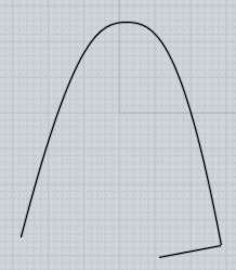
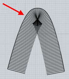
In this case when the fillet gets over about 2.5 units in size it then runs into this situation where the fillet kind of starts to bunch up and kind of fold over itself in this manner.

That kind of bunching can cause problems in various cases in MoI as well, but in some cases like extrusions it is able to be resolved pretty well.


> If that assumption is correct, then does it mean that MoI's
> Blend tool is making some subtle changes to other parts of
> this solid that ACIS and Parasolid wouldn't consider to be
> acceptable?

MoI's fillet is not modifying anything about the original solid other than the trimming away of some area where the fillet is going.

But it does modify the generated rounded fillet surface - in the area where the regular fillet would not fit here:


It stops the fillet pieces with the exact circular cross-sections outside of that self-intersection zone and instead puts in a different kind of surface blend in that corner which adapts itself to the shape more rather than only having only circular cross sections in that spot.

Both ACIS and Parasolid will put in other similar kinds of non-circular cross section surface blends in other circumstances like for some kinds of corner patches at the ends of edges, they just don't have something that recognizes that the fillet is going to cross over itself at some inside region of the edge like this case.

- Michael
  Reply Reply More Options
Post Options
Reply as PM Reply as PM
Print Print
Mark as unread Mark as unread
Relationship Relationship
IP Logged

Previous
Next
 From:  blowlamp
3651.38 
Thanks again for your detailed reply, Michael. It is very much appreciated as I don't as yet even own a licence for MoI!

Martin.
  Reply Reply More Options
Post Options
Reply as PM Reply as PM
Print Print
Mark as unread Mark as unread
Relationship Relationship
IP Logged

Previous
Next
 From:  DannyT (DANTAS)
3651.39 In reply to 3651.37 
Hi Michael,

quote:
But yes this case does show that the big MCAD kernels are not better in every single case 100% of the time...

Yes, this is somewhat true but then the big MCAD kernels do offer more options to achieve the desired result, take NX as an example, you can choose from Edge Blend, Face Blend, Soft Blend and Styled Blend (Blend=Fillet), each command tackles fillets differently, then you have finer control also, but you do have to pay 100 times more than what MoI costs.

Cheers
~Danny~
  Reply Reply More Options
Post Options
Reply as PM Reply as PM
Print Print
Mark as unread Mark as unread
Relationship Relationship
IP Logged

Previous
Next
 From:  Michael Gibson
3651.40 In reply to 3651.39 
Hi Danny, does one of those options in NX (Edge blend, Soft blend, etc...) make the fillet for this particular case work at something larger than radius = 2.5 ?


> then you have finer control also, but you do have to pay
> 100 times more than what MoI costs.

The other part that tends to go along with such things is a decrease in the "ease of use" department - it tends to take a longer learning curve and more dedication of time to learn how to use stuff like that.

Of course if it is central to your job to produce fillets on mechanical parts it can be worth both the money to purchase such tools and the time invested to learn how to work them.

It's not bad to have supplemental tools as well though, geometry comes in such infinite varieties that it's not really possible for there to be 1 single tool that covers every single possible geometric circumstance in the best possible way every single time.

- Michael
  Reply Reply More Options
Post Options
Reply as PM Reply as PM
Print Print
Mark as unread Mark as unread
Relationship Relationship
IP Logged

Previous
Next
 From:  BurrMan
3651.41 In reply to 3651.40 
I filleted this in the Parasolids Kernel and it seemd to still bunch up in that area. I had several options, which would section the fillet up in different ways, but they all seemed to produce some curvature irregularities in this area. Some of the available tools here also were to dynamically re-tolerance the solid to have the fillet succeed. For instance, here it re-toleranced to .04 to allow a 4 inch fillet.


Note the additional sectioning done in the surface construction, though the analysis still shows the issue:


This one is "maintain Parabolic curves" in the fillet options

EDITED: 19 Jun 2012 by BURRMAN

  Reply Reply More Options
Post Options
Reply as PM Reply as PM
Print Print
Mark as unread Mark as unread
Relationship Relationship
IP Logged

Previous
Next
 From:  Michael Gibson
3651.42 In reply to 3651.41 
Hi Burr, well that's interesting that it makes that kind of result, it seems that it knows that the fillet would become self intersecting there and attempts to do something else.

The problem is the bunching at the top here:


Fillet surfaces are basically like a loft through a bunch of cross-sections, and surface lofting just does not behave well when one side of the loft is all compressed together like that, it will tend to generate those kinds of little ripples and lumps.


The one in MoI solves this by putting in a blend curve at the top so that there isn't a compressed side like that:


- Michael

  Reply Reply More Options
Post Options
Reply as PM Reply as PM
Print Print
Mark as unread Mark as unread
Relationship Relationship
IP Logged

Previous
Next
 From:  BurrMan
3651.43 In reply to 3651.42 
Thats really cool that MoI does something like this well that it seems every other fillet'r has issues with. The result I showed is from Delcams Powershape using the Parasolids kernel, Which is more of a mid range modeler like solid edge or solidworks, though it still gives a bunch of fillet options. I could get it to section up in many different ways, not just that "pole position" result, but they all did the bunching. None did what MoI's does.

Maybe Parasolids needs to see this example to incorporate...LOL
  Reply Reply More Options
Post Options
Reply as PM Reply as PM
Print Print
Mark as unread Mark as unread
Relationship Relationship
IP Logged

Previous
Next
 From:  Kevin De Smet (KEV_BOY)
3651.44 
I think another possible reason is the lack of topology, the model does not have very many edges and solid modelers really crave ordered topology.
Like how the sides are just two big surfaces is complicating.
  Reply Reply More Options
Post Options
Reply as PM Reply as PM
Print Print
Mark as unread Mark as unread
Relationship Relationship
IP Logged

Previous
Next
 From:  Michael Gibson
3651.45 In reply to 3651.44 
Hi Kevin, I'm not sure if a change in topology would make much difference in this case, since it's one smooth shape there is not really any obvious topology changes to make unless you would change the shape to be made of line segments and arcs or something like that rather than 1 smooth curve. But then that would be a different model...

- Michael
  Reply Reply More Options
Post Options
Reply as PM Reply as PM
Print Print
Mark as unread Mark as unread
Relationship Relationship
IP Logged

Previous
Next
 From:  Michael Gibson
3651.46 In reply to 3651.43 
Hi Burr,

> Maybe Parasolids needs to see this example to incorporate...LOL

I wouldn't be surprised if they would incorporate it at some point actually... It seems that they are recognizing that the regular fillet would self-intersect and at least trying to do something about it.

It actually tends to be better to get a result back even with those little ripples in it rather than nothing at all because then you may be able to do some surgery on it to trim out the bad part and fill it in with something else.


One of the more interesting parts of this is not really so much that MoI's filleter can generate this case better (which is going to be a rather rare occurrence), but rather that you can actually see the little ripples with MoI's regular display rather than having to go to a special analysis mode or possibly not even being able to see it at all in some programs even in analysis modes.

- Michael
  Reply Reply More Options
Post Options
Reply as PM Reply as PM
Print Print
Mark as unread Mark as unread
Relationship Relationship
IP Logged

Previous
Next
 From:  BurrMan
3651.47 In reply to 3651.46 
Ah yes. The other program presents to you a fillet that "appears" to be very nice. (Unless analyzed)

I find MoI to be very good at inspecting geometry! (hence my V3 wishlist request for sectioning) It really is powerful in this sense.
  Reply Reply More Options
Post Options
Reply as PM Reply as PM
Print Print
Mark as unread Mark as unread
Relationship Relationship
IP Logged

Previous
Next
 From:  d3print
3651.48 
Here`s some samples from CoCreate, ProE and SolidEdge ST1


Will checking also the IronCAD LATER.

Thanks,

d3

  Reply Reply More Options
Post Options
Reply as PM Reply as PM
Print Print
Mark as unread Mark as unread
Relationship Relationship
IP Logged

Previous
Next
 From:  DannyT (DANTAS)
3651.49 In reply to 3651.40 
Hi Michael,
quote:
Hi Danny, does one of those options in NX (Edge blend, Soft blend, etc...) make the fillet for this particular case work at something larger than radius = 2.5 ?

After having a bit of time doing this it seems NX struggles a bit also, it does manage R=3 with Edge blend and Face Blend before the surface gets funky when you go over R=3, the Soft Blend option is at R=4, had no time to analyse the results, so I've attached a .3dm with all three, they are all named according to what method was used to fillet.

Cheers
~Danny~

  Reply Reply More Options
Post Options
Reply as PM Reply as PM
Print Print
Mark as unread Mark as unread
Relationship Relationship
IP Logged

Previous
Next
 From:  Michael Gibson
3651.50 In reply to 3651.49 
Hi Danny, the edge blend and face blend ones (the 2 on the left) are interesting - it kind of looks like it switched to a sort of rail-revolve type generation in that area. Those are nice on the interior portion of the revolve but has a kind of bump or lack of continuity where the corner patch touches the fillet. You can see it clearly if you turn on metallic lighting in MoI and hide the edges:


The soft blend one seems pretty good though, maybe just tiny subtle hint of a lump in one spot. The control points on it are clustered in some areas but it doesn't seem to suffered much for it at least in this particular case:


- Michael

  Reply Reply More Options
Post Options
Reply as PM Reply as PM
Print Print
Mark as unread Mark as unread
Relationship Relationship
IP Logged

Previous
 From:  d3print
3651.51 
Here`s IronCad 1,7 mm round. R1,75mm didn`t work for basic round.


Thanks,

d3


Attachments:

  Reply Reply More Options
Post Options
Reply as PM Reply as PM
Print Print
Mark as unread Mark as unread
Relationship Relationship
IP Logged
 

Reply to All Reply to All


Show messages:  1-16  17-36  37-51