Inset Command
 1-10  11-30  31-50  51-70  71-72

Previous
Next
 From:  Jamie (FUTUREPROOF)
3295.51 In reply to 3295.50 
Hi Michael

Thanks for the clarification, it will be a good addition to the tools with the groove function added in. I glad it will be in V2

I am looking forward to see how V3 shapes up with your ideas on carving with curves. Although I think you should have a good holiday after V2 is released.

Kind regards

Jamie
  Reply Reply More Options
Post Options
Reply as PM Reply as PM
Print Print
Mark as unread Mark as unread
Relationship Relationship
IP Logged

Previous
Next
 From:  ycarry
3295.52 
Hi
Michael this Inset will be great and a big time saver! (maybe in V2?).
About to keep the cut piece after Inset: (Im french and cannot really follow/understand prec. posts about that)
it can be usefull for making lids, trap ddors, to save the cutted part
i.e. battery trap doors with first inset, then another inset bigger for battery housing.
  Reply Reply More Options
Post Options
Reply as PM Reply as PM
Print Print
Mark as unread Mark as unread
Relationship Relationship
IP Logged

Previous
Next
 From:  Michael Gibson
3295.53 In reply to 3295.51 
Hi Jamie, one way that it will be possible to work with curves with this initially would be to use the curves to carve the base solid up into smaller solids, then you can inset the top faces of the smaller pieces.

You can use the Boolean Merge command to cut a solid by a profile curve and leave all the pieces behind.

That looks something like this:


So that combination may be a good way to effectively use curves already.

- Michael

  Reply Reply More Options
Post Options
Reply as PM Reply as PM
Print Print
Mark as unread Mark as unread
Relationship Relationship
IP Logged

Previous
Next
 From:  Yenmonger (OTTERMAN)
3295.54 
I'm going to use this new function like crazy. My sincerest thanks.
  Reply Reply More Options
Post Options
Reply as PM Reply as PM
Print Print
Mark as unread Mark as unread
Relationship Relationship
IP Logged

Previous
Next
 From:  NightCabbage
3295.55 
So glad this made it into V2 (and the current beta)!

Excellent work Michael :D
  Reply Reply More Options
Post Options
Reply as PM Reply as PM
Print Print
Mark as unread Mark as unread
Relationship Relationship
IP Logged

Previous
Next
 From:  BurrMan
3295.56 In reply to 3295.20 
Michael,
I was working the label can model and wanted to inset command the face on the can. The inset command will complete on "inwards" but produce nothing with "outwards". I can offset the surface and shell it to get the job done though. Are you interested in seeing these types of models yet? I know you said it's new and will be refined, So no need to be bombed with insets that fail, but if you want the model "pre-inset", I'll post it.

All sharp corners.

EDITED: 19 Jun 2012 by BURRMAN

  Reply Reply More Options
Post Options
Reply as PM Reply as PM
Print Print
Mark as unread Mark as unread
Relationship Relationship
IP Logged

Previous
Next
 From:  Michael Gibson
3295.57 In reply to 3295.56 
Hi Burr - the "sharp corners" part that I was talking about previously was actually meaning how multiple surfaces touch one another, not necessarily how the trim curves of one surface are arranged...

But yeah if you can post it I'll take a look - most likely it will be a case that is having difficulty with the geometry library's offsetter and probably not much that I can do about it directly but it is worth a check.

It will not be unusual to see failures with the new inset tool because the offset mechanism in the geometry library just has difficulties with many cases.

The Inset command internally uses solid offsetting a couple of times in sequence, so any difficulty in the offset calculation will cause it to fail.

- Michael
  Reply Reply More Options
Post Options
Reply as PM Reply as PM
Print Print
Mark as unread Mark as unread
Relationship Relationship
IP Logged

Previous
Next
 From:  BurrMan
3295.58 In reply to 3295.57 
Here's the file. I only post it in hopes it helps you with something. But not for any particular need I have. No need to post back a file that "Works" for me or anything. It only appeared that it should work from what I understood of your previous explanation, so I brought it up, but I wont inundate you with circumstances where it doesnt work.

EDITED: 19 Jun 2012 by BURRMAN

  Reply Reply More Options
Post Options
Reply as PM Reply as PM
Print Print
Mark as unread Mark as unread
Relationship Relationship
IP Logged

Previous
Next
 From:  Michael Gibson
3295.59 In reply to 3295.58 
Hi Burr, yeah that's actually the _non_ sharp cornered kind of case.

You've got 2 surfaces here joined together:


And check out this edge for example where they join:


The 2 surfaces are completely smooth to one another at that joined edge rather than touching each other at a sharp edge. That can cause additional difficulties.

You can actually get it to work in this case for Direction = Outwards if you use Edit > Separate to break that surface into an individual part rather than having it smoothly connected to the other piece.

I will actually take a closer look at this case though, because the Inset command is supposed to make an attempt to use the surface as an individual part automatically and ignore the connections to neighboring surfaces if it was having problems with the offset.

- Michael

  Reply Reply More Options
Post Options
Reply as PM Reply as PM
Print Print
Mark as unread Mark as unread
Relationship Relationship
IP Logged

Previous
Next
 From:  Frenchy Pilou (PILOU)
3295.60 
In this area TopMod is a crazzy Poly prog for some Inset function ;)

http://www.topmod3d.org/ (free)
---
Pilou
Is beautiful that please without concept!
My Gallery
  Reply Reply More Options
Post Options
Reply as PM Reply as PM
Print Print
Mark as unread Mark as unread
Relationship Relationship
IP Logged

Previous
Next
 From:  JPBWEB
3295.61 
Hello Michael,

I like the new Inset command a lot from the first tries I had. For me it looks like a most promising way to generae quick and clean grooved-in panels in plane fuselages. Unfortunately, it seems to have quite a lot of trouble in some cases but not in others, so that it is a hit and miss matter. Usually, as indicated already, it is obvious that the geometry is way too complex for MoI to make sense of it but some other times it is very puzzling. Consider the following example:


I Boolean_Merged three simple shapes with a cylinder. The rectangle and the circle produced perfect inset panels, with an outer rim and a groove as per the distances indicated, but the oval shape, that seems to be just as smooth and regular as the other two, failed and produced something of a mess, which I found regrettable. There are definitely easy workarounds for cases like this, but still, it is a pity.

I attach the 3dm file in case you want to have a look.

Jean-Paul

  Reply Reply More Options
Post Options
Reply as PM Reply as PM
Print Print
Mark as unread Mark as unread
Relationship Relationship
IP Logged

Previous
Next
 From:  Michael Gibson
3295.62 In reply to 3295.61 
Hi Jean-Paul, yeah unfortunately you will probably run into many things that will not inset, particularly with curved pieces.

The Inset command needs to do a combination of several complex calculations, including a solid offset, then a boolean merge with some coincident surfaces involved, then an additional solid offset that shrinks down the "plug".

There can be problems with any of those steps, but in particular the offset function in the geometry library that I use can only handle pretty simple cases where there is no change in topology in the generated offset.

When you have a face that is completely smooth with its surrounding area, that will require a topology change in the offset. Here I'll try to explain it -

So one part of Inset is that it tries to calculate an offset of the set of faces surrounding your selected one, where the only the selected face is actually offset and the other surrounding faces stay in place, like this:


Then each of those surfaces gets extended and intersected with each other to form connections in the offset as necessary.

But the geometry library offset is set up to expect that for each vertex and edge of the original that there will be a matching vertex and edge in the offset result. That's not always the case though, like when you have a smoothly connecting face, it will try to do something like this:


So note there that when the offset tries to get extended in that case it won't actually intersect with the neighboring face, really some additional faces need to be inserted in there, which means a change in topology which is not currently handled directly by the offsetter.

The Inset command will try to solve this when possible by trying to take the face as a completely separate surface and ignoring its connections to adjacent faces. It's easier for that additional topology to be inserted properly when there were completely unattached edges in those spots. That's the only reason why the other examples on the same surface for the circle and rectangle parts actually worked. Sometimes you may need to manually separate out a smooth surface though.

I think in your case with the ellipse part that it's probably running into the other difficult area of doing the merge with coincident surfaces though, that's also a difficult calculation as well...


Still there may be some potential improvements that I can make, possibly the merging difficulties may be easier to do something about than offset problems.


Currently it will tend to have an easier time with more blocky types of shapes.


- Michael

EDITED: 6 Mar 2010 by MICHAEL GIBSON


  Reply Reply More Options
Post Options
Reply as PM Reply as PM
Print Print
Mark as unread Mark as unread
Relationship Relationship
IP Logged

Previous
Next
 From:  Michael Gibson
3295.63 In reply to 3295.61 
Hi Jean-Paul, I examined your elliptical inset problem on a cylinder, and it seems to be failing due to an incorrect offset being created by the geometry library.

So unfortunately that's not going to be something easy for me to fix anytime soon.

As part of the Inset process, it creates a "plug" object, which in your elliptical case looks like this: (3DM geometry file also attached):


Then it wants to produce an offset of that plug, keeping the top and bottom surfaces in place and only offsetting the vertical one.

That offset is getting all messed up, you can kind of see a similar problem if you open up the attached 3DM file and just offset it using the regular Construct > Offset command, it creates this:


You can see that's not a proper offset.

When the geometry library's offset mechanism creates a bad result like this, it will prevent the Inset command from working properly.


< ..... After some more examination ....>


But one of the problems in this case seems to be related to the vertical surface being a single closed surface.

It does look like there is a possible work-around for some cases like this which is to split a closed edge so that it becomes 2 edges intead of one, you can do that by selecting the edge and running Trim, with the "Add trim points" option to pick a splitting point on the side opposite of where the edge's seam is (to see the seam extrude it and watch where the seam edge is on the extruded surface). Like this:


Once that edge is split into 2 edges instead of a single closed one, then Inset seems to actually work on that face:


So that's something you can try for that case right now, and I'll take a look at doing that closed edge splitting automatically inside of the Inset command.

- Michael

  Reply Reply More Options
Post Options
Reply as PM Reply as PM
Print Print
Mark as unread Mark as unread
Relationship Relationship
IP Logged

Previous
Next
 From:  BurrMan
3295.64 In reply to 3295.63 
Michael,
Did you know that if you run "seperate" on your plug, that it then offsets nicely?
  Reply Reply More Options
Post Options
Reply as PM Reply as PM
Print Print
Mark as unread Mark as unread
Relationship Relationship
IP Logged

Previous
Next
 From:  BurrMan
3295.65 In reply to 3295.64 
ooops. I see that the seperation of the surfaces you are also refering to as the poor result. Not just the "Streamer".
  Reply Reply More Options
Post Options
Reply as PM Reply as PM
Print Print
Mark as unread Mark as unread
Relationship Relationship
IP Logged

Previous
Next
 From:  Michael Gibson
3295.66 In reply to 3295.64 
Hi Burr, yeah when you separate things into individual surfaces, it reduces a lot of the complexity involved in the offset because it doesn't have to try to extend stuff anymore.

But without extensions there will be all kinds of gaps between the offset pieces, like if you separate a box into 6 individual surfaces and offset them you'll see that kind of result.

- Michael
  Reply Reply More Options
Post Options
Reply as PM Reply as PM
Print Print
Mark as unread Mark as unread
Relationship Relationship
IP Logged

Previous
Next
 From:  BurrMan
3295.67 In reply to 3295.66 
Thought I was a genius! Found out I was a novice....
  Reply Reply More Options
Post Options
Reply as PM Reply as PM
Print Print
Mark as unread Mark as unread
Relationship Relationship
IP Logged

Previous
Next
 From:  JPBWEB
3295.68 
Michael,

Thanks for looking into this even further.

I tried as you suggested. Indeed, splitting the edges seem to help a little, but even the simple thickness seems to fail under a certain number (about 1mm in the example, and it does generate parasite surfaces on the rims that do carry over to the rest when the groove and separate height options come into play. I tried again with a fresh cylinder and oval, but it gets the same weird things happening.

With a clean smooth surface and simple shape to inset, there are easy other ways to achieve what I want, but when it comes to complex shapes like rudders or airbrakes on tailplanes and wings of aircraft, it would really help to have an automatic inset working there, but I understand that it is probably not that easy to get.

Nonetheless, in those cases when it works I am confident that the Inset command will help me a lot.
  Reply Reply More Options
Post Options
Reply as PM Reply as PM
Print Print
Mark as unread Mark as unread
Relationship Relationship
IP Logged

Previous
Next
 From:  Michael Gibson
3295.69 In reply to 3295.68 
Hi Jean-Paul,

quote:
Indeed, splitting the edges seem to help a little, but even the simple thickness seems to fail under a certain number (about 1mm in the example

In your example, 1mm is a pretty large distance in comparison to the shape - in general a surface offset that goes a long distance away proportionally can be more difficult to calculate.

As the distance increases, any little wobbles in the surface normal become magnified, and it also can be difficult when things are approaching the same distance as the radius of the bend in the curve.

Here's kind of the classic example of how a large distance being offset around a tight bend causes bunching:


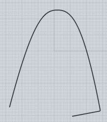
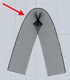
I think with 1mm in your particular example here, it is not enough distance to be fully self-intersecting like in this case above, but it still is approaching towards that and becoming more bunched.

Unfortunately calculating surface offsets has several complicated issues like this that can interfere with getting a clean result.

So you may generally just expect that trying to do a surface offset that goes a significant distance proportionally away from the original on a bendy thing is going to be problematic.


quote:
With a clean smooth surface and simple shape to inset, there are easy other ways to achieve what I want, but when it comes to complex shapes like rudders or airbrakes on tailplanes and wings of aircraft, it would really help to have an automatic inset working there, but I understand that it is probably not that easy to get.


It's just not going to be realistic to expect much on complex surfaces with tight bends in them - that's not really where I expect for this to be used.

It is really meant more to be used with clean and simple shapes, but it does help to add quite a lot of interesting details really quickly to a simple shape, to turn a simple form into a more interesting one.

Here's a good example of the kind of thing that it is more oriented towards:


Things like this command tend to raise a difficult question for me - should I shy away from adding in tools that won't work with complex bendy surfaces like a rudder or an airplane wing, but that do work well with blocky objects?

If I only waited until something like this worked on all kinds of shapes and bendy surfaces, it would probably be a long time before it would ever be released.

- Michael
  Reply Reply More Options
Post Options
Reply as PM Reply as PM
Print Print
Mark as unread Mark as unread
Relationship Relationship
IP Logged

Previous
Next
 From:  Michael Gibson
3295.70 In reply to 3295.56 
Hi Burr, also I was able to take a look at the case you reported earlier here:
http://moi3d.com/forum/messages.php?webtag=MOI&msg=3295.56

where you were getting a result when going inwards, but not when going outwards.

That particular one will be fixed up in the v2 final release, there was some extra work that needs to be done for this kind of smooth connecting surface stuff that was not happening for the outwards mode but it will now.

- Michael
  Reply Reply More Options
Post Options
Reply as PM Reply as PM
Print Print
Mark as unread Mark as unread
Relationship Relationship
IP Logged
 

Reply to All Reply to All


Show messages:  1-10  11-30  31-50  51-70  71-72