some problem with Boolean Union and Fillet

Next
 From:  Renato M. Setoue (INONSENSE)
1767.1 
Hello there,

My name is Renato, I´m from Brazil. I was googling about Rhino, trying to find some similar software and found out about MoI. After some research about it I decided to download the trial version and give it a try. I don´t know much about 3D modeling yet, I started it last week with Sketch Up, but it isn´t the best for modeling, it´s hard to make the things work or to make the things look good with some rounded faces, etc.... So I had some hard time making a 2.1 speakers that i found in the Internet. It was my first try to make any object in any software so it´s not very nice [I attached it] but as first experience i like it, I´ll try to make it with MoI someday.

I saw some of video tutorials to try to understand how it works and started modeling right away, I really liked the UI and as you get used to that you find the things very intuitive. (I´ll try Rhino too, but I got scared when I saw all that icons, bars an stuff so decided to start with MoI... hehehe...). I´m really enjoying "to play" with 3D modeling... hehehe...

Well, here it is, my little problem.
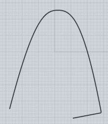
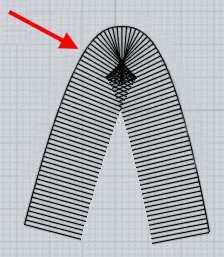
Some times when I finish the things or want to test the Fillet, it just doesn´t work, the corners are still there. Usually I use Boolean Union to make everything an unique object and then I use Fillet, to change the surface, to make it more "rounded". But sometimes, when I do that, it doesn´t work. I tried to figure it out, tried to see if the line are all there, etc... I also tried to catch just the lines and Join all of them and some how just part of them really joined. I downloaded the trial version that can´t make saves so I can´t attatch the file. I will start from the begining again but I just wanted to know what I´m doing wrong ´cause it also happened when I was following the video tutorial for the first time. In that time I just started again and it worked but I didn´t figure it out what I was doing wrong.

Thanks
Image Attachments:
Size: 84.3 KB, Downloaded: 55 times, Dimensions: 800x600px
  Reply Reply More Options
Post Options
Reply as PM Reply as PM
Print Print
Mark as unread Mark as unread
Relationship Relationship
IP Logged

Previous
Next
 From:  Michael Gibson
1767.2 In reply to 1767.1 
Hi Renato, do you have a .3dm model file of one of the shapes where the fillet did not work?

If you could post the model file, that would help a lot to give you a better answer.

Fillets are a sensitive and finicky area, there are a lot of things in a model that can prevent fillets from being calculated properly.

Sometimes it is a matter of asking for too large of a radius than will fit. Often times it is surprising how much room a fillet of say radius 1 or 2 will fill up. If your fillet does not work, try using a smaller radius to see if that will work. If you have little faces that the fillet would totally consume, that will cause the fillet to fail and you need to use a smaller distance.

Also if you have an area of tight curvature, that can limit the size of fillet that can fit there.

If you have a corner junction with many many edges coming together at a single point, that can prevent fillets from working because MoI's fillet engine does not handle every single kind of corner junction.

If you have surfaces or edges that loop back on themself and "self intersect" then that can prevent fillets from working.

It is impossible to say which of these or other problems you may have run into without actually examining the model. There is a good chance that you just ran into a fillet bug as well, I am just about ready to apply an update with some fillet bug fixes for the v2 beta, so I think that should help out in this area.

- Michael
  Reply Reply More Options
Post Options
Reply as PM Reply as PM
Print Print
Mark as unread Mark as unread
Relationship Relationship
IP Logged

Previous
Next
 From:  Renato M. Setoue (INONSENSE)
1767.3 In reply to 1767.2 
Hi Michael,

I can´t save the file because I´m using the Alternate Trial Version so I made a printscreen. I was modeling my mouse cuz it has a nice design. It was hard cuz it has a lot of diferents curves but I lost it. Windows stopped working while I was reading my e-mail and as I can´t save I lost it. Now I´m trying something easier, cuz if I had any problem I wouldn´t feel so bad about it. I´m modeling that "supporter" that comes with Intuoes.

I started it again but this time, after every step that I wanted to use Fillet I used it. Because I was finishing all the modeling and then using Fillet [it wasn´t working]. With this new strategy it worked pretty well until the last part [printscreen]. The yellow thing is what I´m trying to use Fillet and it´s not working. I also tried the whole thing around but it didn´t work.


I hope this printscreen can help somehow.
Attachments:

  Reply Reply More Options
Post Options
Reply as PM Reply as PM
Print Print
Mark as unread Mark as unread
Relationship Relationship
IP Logged

Previous
Next
 From:  Michael Gibson
1767.4 In reply to 1767.3 
Hi Renato - it looks like you have done a previous fillet around the top edge of a pretty small radius, then did the boolean cut after that.

That previous tight fillet now makes a very tight area of edge curvature in the booleaned out piece.

Your next fillet radius will need to be even smaller than that previous one to fit.

A fillet basically needs to extend by a constant distance away from an edge.

So for example if you have an edge like this with the line being the distance you want:


That kind of situation is going to make the filleter try to produce something like this:


You can see all that bunched up and messed up area there - that kind of thing is going to cause problems.


In the case that you show there, I would recommend not doing that previous fillet before doing the boolean. Keep the top edges sharp, then do the boolean, then fillet all those edges including the top and around the boolean cut all at the same time instead of at different times, that should help out a lot.

- Michael
  Reply Reply More Options
Post Options
Reply as PM Reply as PM
Print Print
Mark as unread Mark as unread
Relationship Relationship
IP Logged

Previous
Next
 From:  BurrMan
1767.5 In reply to 1767.3 
Hey Renato,
I'm new to MoI also and also working on how it does things. As I work on Booleans and fillets I'm finding that it leaves lines that arent part of the object and when you select what you want to fillet, your selecting seperate lines. not the objects boundry line that you want to fillet. What I do is select those lines and delete them, then select again and try your fillet sizes. (The easy way to select lines is to click in the surface which highlights the solid, then point at the lines and they become the "Mode" of selection. Even using window drag!)


By the way, I also did it after the top fillet, though it worked here. (My model may be significantly bigger)
I did think of that before yet forgot it in my process.

Am I correct about the left over lines Michael? I also forgot to mention the original lofting or sweeping lines can get in the way also.

EDITED: 19 Jun 2012 by BURRMAN

  Reply Reply More Options
Post Options
Reply as PM Reply as PM
Print Print
Mark as unread Mark as unread
Relationship Relationship
IP Logged

Previous
Next
 From:  Michael Gibson
1767.6 In reply to 1767.3 
Hi Renato, sorry I didn't quite read your message carefully enough, I was just looking at your image. One other comment, you wrote:

> I started it again but this time, after every step that I wanted
> to use Fillet I used it. Because I was finishing all the modeling
> and then using Fillet [it wasn´t working]. With this new strategy
> it worked pretty well until the last part [printscreen].

Actually normally I would recommend doing the fillets at the end... I'm not sure why that did not work for you previously, again it is hard to know without being able to examine the particular case.

But when you end up with different fillets that are going to kind of cross over and touch each other, those should be applied all at the same time except in situations where you are going to have something like a much larger radius on some of them and then a final small radius on the cut-out piece.

Like for example here:


This one was ok to apply in different stages because the first one around the top edges was a much larger radius than the second one around the booleaned out edges.


But if you want them all to be of the same small radius then those are good to apply all at the same time.

- Michael

  Reply Reply More Options
Post Options
Reply as PM Reply as PM
Print Print
Mark as unread Mark as unread
Relationship Relationship
IP Logged

Previous
Next
 From:  Michael Gibson
1767.7 In reply to 1767.5 
Hi Burr,

> Am I correct about the left over lines Michael? I also forgot to
> mention the original lofting or sweeping lines can get in the way also.

Yes - but the normal thing is for those left over lines to be all your original curves that were used during your modeling.

Things like booleans and fillets should not be creating additional left over lines - if they do then that would definitely be a bug. If you have an example of something like that, please let me know and if you have an example it might help me to track that down.

But it is pretty normal to have many left over curves from previous operations, like extruding, revolving, something that you drew as a boolean cutting object, etc...

Those curves can pretty easily get in your way and prevent you from selecting the "edge" of an solid instead of that original different curve object, so it is a good idea to hide or delete those things when you are finished with them.

- Michael
  Reply Reply More Options
Post Options
Reply as PM Reply as PM
Print Print
Mark as unread Mark as unread
Relationship Relationship
IP Logged

Previous
Next
 From:  BurrMan
1767.8 In reply to 1767.7 
Renato,
Please disregard what I said and go with michael's advice.

Michael,
Seems more of an anomoly thing than a bug. and yes it has to do more with the fillet, then boolean, then fillet again. For instance here are three files. with the "boolean lines for MG_2.3dm" I generated the other 2. I also generated the same operation with 5 other attempts that worked fine.

One file lost a surface during the action. the other is the failure to fillet thing. After the failure I may have joined the 6 edges and deleted them then tried again.

Anyway, after doing it for 10 minutes, then paying closer attention to selecting things in some kind of fashion, it seems to do it ok. And if I do like you suggested and wait to do them all at the same time it seems to function correctly.

My previuous statements about the "Boolean" leaving lines does not seem to be accurate.

Thanks for the attention.
Burr
  Reply Reply More Options
Post Options
Reply as PM Reply as PM
Print Print
Mark as unread Mark as unread
Relationship Relationship
IP Logged

Previous
Next
 From:  Michael Gibson
1767.9 In reply to 1767.8 
Hi Burr, well definitely the issue that you mentioned is something to look out for. It is easy to select a "curve" object instead of an "edge" object, especially since many construction techniques will put an edge of the resulting solid in the same spot as where your original generating curve was at.

It's probably one of the easiest areas to get tripped up on in MoI currently.

At some point I'm going to need to try and improve that situation... It's just a difficult thing to handle without popping up some kind of additional UI which I have tried to avoid as much as possible up to now.

- Michael
  Reply Reply More Options
Post Options
Reply as PM Reply as PM
Print Print
Mark as unread Mark as unread
Relationship Relationship
IP Logged

Previous
Next
 From:  BurrMan
1767.10 In reply to 1767.9 
I think your properties panel will handle that for me. Knowing what I'm looking at. Info on whats selected.

Thanks for your help!
  Reply Reply More Options
Post Options
Reply as PM Reply as PM
Print Print
Mark as unread Mark as unread
Relationship Relationship
IP Logged

Previous
Next
 From:  Renato M. Setoue (INONSENSE)
1767.11 In reply to 1767.6 
Hi Michael,

I finally done it. Actually I had to come out with another way to make it, it was just a little change, but made the things work. I´ll use the printscreens to try to show the difference and after this little exercice I think I´m understanding better what Fillet can do or what are the conditions to do it.

In the first image [1.1] you can see I the things I used to make it.


1.1


In the second one [2.1] you can see the way I was doing that "border" before. I was using Boolean Diff with the sphere. In the third image [2.2] you can see what happened, I tried but I couldn´t use Fillet in that "border".


2.1


2.2


In the 3.1 you can see what I changed and then the results [3.2 and 3.3]. Well, the last one, as I can´t save and render it, I just used HIDE to hide the lines... hehehe...


3.1


3.2


3.3

  Reply Reply More Options
Post Options
Reply as PM Reply as PM
Print Print
Mark as unread Mark as unread
Relationship Relationship
IP Logged

Previous
Next
 From:  Ed
1767.12 In reply to 1767.9 
"... It is easy to select a "curve" object instead of an "edge" object, especially since many construction techniques will put an edge of the resulting solid in the same spot as where your original generating curve was at. It's probably one of the easiest areas to get tripped up on in MoI currently."

Would changing MoI to make the two types of lines different colors be a solution?

Ed
  Reply Reply More Options
Post Options
Reply as PM Reply as PM
Print Print
Mark as unread Mark as unread
Relationship Relationship
IP Logged

Previous
Next
 From:  Michael Gibson
1767.13 In reply to 1767.12 
Hi Ed,

> Would changing MoI to make the two types of lines
> different colors be a solution?

I'm not sure about that... It is tough to come up with colors that people will attach meaning to. If you see a bunch of different colors and you don't really have a meaning to attach to them, it doesn't really solve the fundamental problem very well.

Because of that, I've kind of tried in general to keep using colors down to a kind of minimal level that have more distinct meanings, like yellow = selected is pretty straightforward.

But I don't think it would be a bad idea to have an option to have them displayed in different colors if you want, I mean if you do know what those colors mean then that could indeed be helpful.

Also though, I want to support the ability to change colors on different objects as a way for you to separate them into different groups for your own kind of labeling purposes... That's another reason why I have kind of stayed away from using too many colors for the "system" because it then tends to get confused with your own coloring schemes.

One of the first steps that will help out with this is the properties panel that I want to do which will show up to show you some information about the selected objects. So I'll probably wait and see how that works first before really doing more in this particular area.

- Michael
  Reply Reply More Options
Post Options
Reply as PM Reply as PM
Print Print
Mark as unread Mark as unread
Relationship Relationship
IP Logged

Previous
Next
 From:  Ed
1767.14 In reply to 1767.13 
I think the option to assign colors is a good idea.

Looking forward to a properties panel. I had a 2D shape that failed to obtain end caps during extrude. I was sure I had closed my curves with "blend" but one very, very small gap existed. I could have used a dialog to tell me the shape was not closed.

Ed
  Reply Reply More Options
Post Options
Reply as PM Reply as PM
Print Print
Mark as unread Mark as unread
Relationship Relationship
IP Logged

Previous
Next
 From:  BurrMan
1767.15 In reply to 1767.14 
Renato,
Awesome with all booleans. Dont forget to check out the sweep and loft tools in MoI.

The same thing can be done by using loft with 4 circles.


I pick the bottom, then top down, then choose loft. Choose straight as a style. and chamfer your edges. (dont forget to erase the original circles)

Burr

EDITED: 19 Jun 2012 by BURRMAN

  Reply Reply More Options
Post Options
Reply as PM Reply as PM
Print Print
Mark as unread Mark as unread
Relationship Relationship
IP Logged

Previous
Next
 From:  Renato M. Setoue (INONSENSE)
1767.16 In reply to 1767.15 
BurrMan,

That´s a nice way to do it, I like when something can be done in a different way, there is a lot of different possibilities.

I used Loft in the first piece, using 2 circles. But I don´t know if doing only with Loft it would really be the same. The tip of the cone is like a little sphere, but it can be done after using the loft, so no big deal. But I used a sphere with Boolean Diff to make the concavity, if you use Loft for that wouldn´t it be a base of a cone? A cone upside down without its top?

Anyway, I liked the idea.
I´m trying to make more objects to learn more of each tool. As I said, I´ve no previous experience in 3D modeling so while I´m exploring MoI I´m also exploring 3D modeling... hehehe...
I just hope that when I give a try in Rhino, for exemple, it doesnt feel too strange or difficult... lol...

Next thing I´m going to try to make is a Wi-Fi USB adapter, my mouse, my cellphone... All the objects around me... hehehe... I hope that by the end of the month I´m able to make more complex things, the problem and the dilemma is: not be able to save or just have 30-day trial... cuz if I have to turn the computer off or Windows decide to stop working [like it does sometimes... bad temper... ] I´ll have to start it again... lol...
  Reply Reply More Options
Post Options
Reply as PM Reply as PM
Print Print
Mark as unread Mark as unread
Relationship Relationship
IP Logged

Previous
 From:  BurrMan
1767.17 In reply to 1767.16 
>But I used a sphere with Boolean Diff to make the concavity, if you use Loft for that wouldn´t it be a base of >a cone? A cone upside down without its top?

Yes Renato. I suppose I just dont pay close enough attention. Just passing on my excitement as I am learning MoI along with you. I hope you can save up and Buy MoI and then we can swap stuff as we chat. Good luck with the surrounding items!

Talk to you later,
Burr
  Reply Reply More Options
Post Options
Reply as PM Reply as PM
Print Print
Mark as unread Mark as unread
Relationship Relationship
IP Logged
 

Reply to All Reply to All