Creating a Crusader Helmet

Next
 From:  beowulf
1338.1 
hello all, i wondered if you could give me a few pointers on modelling a Crusader style helmet?

I'm totally new to MOI and I usually use Cinema 4D for all of my modelling, so I can't really get my head round it.

The Crusader Helmet I am trying to model is like the one in the link below.

http://www.swordsandarmor.com/images/H910902_Crusader_Helm.JPG

Hope someone can give me advice etc.

Thanks.
  Reply Reply More Options
Post Options
Reply as PM Reply as PM
Print Print
Mark as unread Mark as unread
Relationship Relationship
IP Logged

Previous
Next
 From:  Brian (BWTR)
1338.2 In reply to 1338.1 
http://moi3d.com/forum/index.php?webtag=MOI

There is an awefull lot of wonderful stuff to plough through here--about as good a learning source as I have seen for any app---but I think there is another helmet done by somebody quite recently.
  Reply Reply More Options
Post Options
Reply as PM Reply as PM
Print Print
Mark as unread Mark as unread
Relationship Relationship
IP Logged

Previous
Next
 From:  Michael Gibson
1338.3 In reply to 1338.1 
Hi beowulf, make sure to check out the tutorial videos here:
http://moi3d.com/1.0/docs/tutorials.htm

Those give a pretty good general introduction to the general methods used - you basically will draw some key profile curves of your shapes, then create surfaces from them, and cut/merge different pieces together.

Here is an overview of one way to make a helmet shape, I did this really quickly and it doesn't have proper proportions but I think it might give you some ideas on how to proceed.

I started by drawing a profile curve in the top view for the outline of half the helmet:


Then I switched to the 3D view, and held down Ctrl while dragging on that profile in the Z direction to make several copies vertically. I then turned on the control points of all these curves and adjusted the copies so that they tapered in somewhat as they moved upward:


Then create a surface through these curves using the Construct / Loft command:


Select the surface and use Transform / Mirror to make a mirrored copy of it, and you have the base shape of the helmet:


To make a slightly rounded top piece, I drew 2 curves that crossed each other, arranged like this:


Then I selected one of those curves, ran Construct / Sweep, and picked the other curve as the rail. This created a rounded sweep surface that looks like this:


This shape punches through the top of the helmet, the whole thing together now looks like this:


Now I want to merge those pieces together - select them both and run Edit / Trim, and at the "select cutting objects" prompt, push Done to do a mutual trim (indicating that these objects will act as both an object to cut as well as a cutting object itself). Select the outside bits to discard, and you are left with this:


Those surface pieces can now be selected and glued together by using Edit / Join.

Then to get a slightly rounded weld type shape, I selected the object an used Construct / Fillet to round off the sharp edges. Now it looks like this:


To make a kind of outward flare at the bottom, I selected the bottom edge curves, and use Edit/Join to create a longer curve object out of them:


Then I drew a small line segment in the side view that protruded out at an angle:


Then I selected that little line, ran Construct / Sweep, selected the joined bottom curve as the rail, and that created this flare thing at the bottom:


All together it looks like this now:


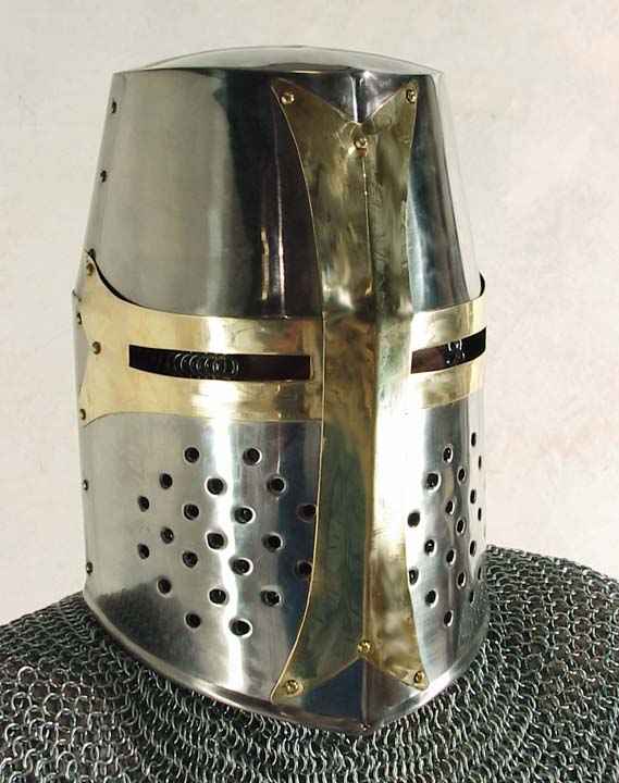
To put in the eye holes and grills you would draw some curves in the front view and then either use Trim on the helmet to cut it, or if you have made a solid you might extrude the curves into cylinder type shapes and then use a boolean to cut them away from the main helmet.


I hope this gives you some ideas on how to proceed - again the basic process is to draw key profile curves that define the shape, then use construction commands to build surfaces or solids from those curves.

You usually don't try to build everything all in just one single shot - notice how I built the side part of the helmet first and the top capping part later and trimmed them to each other. That is a typical method to build smaller pieces and combine them together using trimming or booleans, and round off the sharp edges between them with fillets.

- Michael

  Reply Reply More Options
Post Options
Reply as PM Reply as PM
Print Print
Mark as unread Mark as unread
Relationship Relationship
IP Logged

Previous
Next
 From:  beowulf
1338.4 
Brian, thanks for the info.

Michael, wow you've blown me away. That is what I call support. I was only expecting a few hints, and I thank you for the effort you have put into it, knowing that you are obviously a busy man.

I couldn't get used to it all being one model at first within MOI, unlike C4D which is multiple objects in my case.

Thanks again, I will view the tutorials as you suggest.
  Reply Reply More Options
Post Options
Reply as PM Reply as PM
Print Print
Mark as unread Mark as unread
Relationship Relationship
IP Logged

Previous
Next
 From:  beowulf
1338.5 
Hi Michael,

Just a slight problem I have encountered. I went through a similar route as you, using a Loft to create the helmet and all seemed fine until I went to export the mesh. The preview shows the topology as crooked.

The attached pictures should show you what I mean.

Thanks.

  Reply Reply More Options
Post Options
Reply as PM Reply as PM
Print Print
Mark as unread Mark as unread
Relationship Relationship
IP Logged

Previous
Next
 From:  Michael Gibson
1338.6 In reply to 1338.5 
Hi Beowulf - that looks like a side effect from doing the loft using full closed loops instead of half curves like I was using.

When you loft between closed loops, MoI needs to find an alignment point between each section, so that there isn't any twisting between sections.

MoI does some calculations to reduce twisting, but if you want a particular exact alignment you may need to adjust it manually.

When you do a Loft using closed sections, you should see a display that looks like this (while you are in the Loft command, before you push "Done" to finish it):


Those points that are displayed are the alignment points between each section - switch to the top view:


Then click and drag on those points to line them up some precise reference line, like the world y axis line:


I think that will tune up the topology to be what you want.

If you still have difficulty with this part, please post your curves as a .3dm attachment here (or e-mail to me at moi@moi3d.com) so I can check out what is happening.


When you loft between open curves there isn't this same issue because it is very clear to MoI how to connect 2 open curves together, just by aligning an endpoint to another endpoint.

- Michael

  Reply Reply More Options
Post Options
Reply as PM Reply as PM
Print Print
Mark as unread Mark as unread
Relationship Relationship
IP Logged

Previous
Next
 From:  Brian (BWTR)
1338.7 In reply to 1338.5 
Does the edge direction of the polygons have any bearing on the end smoothness? If your file had been saved to tris I think it would have looked just as 'poly-twisted" but also not have any effect on end results. I regularly see this sort of thing but have never taken any notice of it as a potential problem?

I look forward to a properly informed reply.
  Reply Reply More Options
Post Options
Reply as PM Reply as PM
Print Print
Mark as unread Mark as unread
Relationship Relationship
IP Logged

Previous
Next
 From:  Michael Gibson
1338.8 In reply to 1338.7 
Hi Brian, it doesn't particularly have any effect on regular rendering.

But if you wanted to use polygon modeling tools to do some further editing of the model in the polygon environment, then of course it is nice to have the polygons as well organized and structured as possible.

There are also some other cases where it can make a difference, like you may want to do some special rendering effects where you actually display the wireframe to get a kind of technical design look.

- Michael
  Reply Reply More Options
Post Options
Reply as PM Reply as PM
Print Print
Mark as unread Mark as unread
Relationship Relationship
IP Logged

Previous
Next
 From:  Brian (BWTR)
1338.9 In reply to 1338.8 
Thanks Michael.
It follows, for how I generally work, that I dont really need to add this extra "worry detail" to my methods.
  Reply Reply More Options
Post Options
Reply as PM Reply as PM
Print Print
Mark as unread Mark as unread
Relationship Relationship
IP Logged

Previous
Next
 From:  Brian (BWTR)
1338.10 In reply to 1338.9 
Obviosly I am trying this Helm idea as well.
When I try to boolean the holes in the helm I also get a set of holes at the back--seems very odd?

EDITED: 22 Nov 2008 by BWTR

  Reply Reply More Options
Post Options
Reply as PM Reply as PM
Print Print
Mark as unread Mark as unread
Relationship Relationship
IP Logged

Previous
Next
 From:  Brian (BWTR)
1338.11 In reply to 1338.10 
I guess I worked it out. You have to start with an extrudedobject before starting the array!
Anyway, quite happy with the quick exercise as per the jpeg. More learning into the basket.

EDITED: 22 Nov 2008 by BWTR

  Reply Reply More Options
Post Options
Reply as PM Reply as PM
Print Print
Mark as unread Mark as unread
Relationship Relationship
IP Logged

Previous
Next
 From:  Brian (BWTR)
1338.12 In reply to 1338.11 
And some rendering fun with Carrara5Pro.

EDITED: 31 Dec 2008 by BWTR

  Reply Reply More Options
Post Options
Reply as PM Reply as PM
Print Print
Mark as unread Mark as unread
Relationship Relationship
IP Logged

Previous
 From:  Michael Gibson
1338.13 In reply to 1338.10 
Hi Brian,

> When I try to boolean the holes in the helm I also get a
> set of holes at the back--seems very odd?

It looks like you figured it out already, but just in case - what seems to have happened here is you arrayed not only your cylinder, but the original circle curve that created the cylinder as well.

Then probably those circle curves got selected as cutting objects in addition to the cylinders.

When you use a curve as a cutting object in a boolean operation, it will slice all the way through the object, it won't only cut just the front side of it.

Nice flag at the top, you are really getting the hang of things!

- Michael
  Reply Reply More Options
Post Options
Reply as PM Reply as PM
Print Print
Mark as unread Mark as unread
Relationship Relationship
IP Logged
 

Reply to All Reply to All