Fillet for bicycle brake block

Next
 From:  Koi
10685.1 
Hey guys,
I got a question: I want to model a biycle brake block as it it on the photo. I think the block was bent. thus a similar principle as one folds a cardboard box.
So I tried to built it in parts. But when I make a fillet for the rounding, its on the full part (red line). is there a way to stop the continuous connection? Or am I doing it the wrong way?

Best regards and thank you so much!

koi
Attachments:

Image Attachments:
Size: 204.6 KB, Downloaded: 32 times, Dimensions: 960x1280px
Size: 207.3 KB, Downloaded: 24 times, Dimensions: 960x1280px
Size: 145.7 KB, Downloaded: 28 times, Dimensions: 838x432px
Size: 120.2 KB, Downloaded: 30 times, Dimensions: 691x456px
Size: 527.5 KB, Downloaded: 21 times, Dimensions: 960x1280px
Size: 125.9 KB, Downloaded: 28 times, Dimensions: 691x456px
  Reply Reply More Options
Post Options
Reply as PM Reply as PM
Print Print
Mark as unread Mark as unread
Relationship Relationship
IP Logged

Previous
Next
 From:  Phiro
10685.2 
Did you test to bend it using the flow function.

You write the real piece has to being bent.
Why not trying the same process ?

I will test it...
  Reply Reply More Options
Post Options
Reply as PM Reply as PM
Print Print
Mark as unread Mark as unread
Relationship Relationship
IP Logged

Previous
Next
 From:  Michael Gibson
10685.3 In reply to 10685.1 
Hi Koi, so the first thing that I got confused about with your question is I could not see a red line anywhere. You mean the blue line, right?

And if I understand correctly it's just the brake pad part that you're working on at the moment which is formed from sheet metal with bends.

I think you kind of need a little more separation between the tabs to better simulate sheet metal manufacturing.

Let me see if I can find a reference image for you.

- Michael
  Reply Reply More Options
Post Options
Reply as PM Reply as PM
Print Print
Mark as unread Mark as unread
Relationship Relationship
IP Logged

Previous
Next
 From:  Michael Gibson
10685.4 In reply to 10685.1 
Hi Koi, take a look at these examples and note the spacing in the corner areas between the tabs. I think you're basically missing that spacing.

http://moi3d.com/forum/index.php?webtag=MOI&msg=8126.3
http://moi3d.com/forum/index.php?webtag=MOI&msg=10666.4

Look at the corner areas in particular, and compare to your structure which has material in the corners where I think it needs to be empty:


That's why it's not working quite right when you fillet things, if you had the empty margin spaces in the corners it would help the fillets to be separate and not to run into each other directly like you currently have.

Hope that helps! - Michael
Attachments:

  Reply Reply More Options
Post Options
Reply as PM Reply as PM
Print Print
Mark as unread Mark as unread
Relationship Relationship
IP Logged

Previous
Next
 From:  Phiro
10685.5 
Here is a possibility of flow process following a bending process.
It has to be tuned to have something as you want, I think.
Tuning the curves, arcs, etc.


  Reply Reply More Options
Post Options
Reply as PM Reply as PM
Print Print
Mark as unread Mark as unread
Relationship Relationship
IP Logged

Previous
Next
 From:  Koi
10685.6 
Hey guys,
thank you so much for these fast answers!

Michael, I´m sorry for my bad english, but you got it, that´s what I tried to say... I understand the problem- and your solution!

Phiro, thank you as well! I will try it like that, it looks really realistic!

I love this forum, thank you so much and have a nice day!

Koi
  Reply Reply More Options
Post Options
Reply as PM Reply as PM
Print Print
Mark as unread Mark as unread
Relationship Relationship
IP Logged

Previous
Next
 From:  mk (MARKY)
10685.7 In reply to 10685.5 
Hi Phiro,

Can you elaborate the flow process here a little more?

Marek
  Reply Reply More Options
Post Options
Reply as PM Reply as PM
Print Print
Mark as unread Mark as unread
Relationship Relationship
IP Logged

Previous
Next
 From:  Phiro
10685.8 In reply to 10685.7 
Hi Marek,

I used Koi's file to have the profile he has made.
I made a boolean union to have a single profile.
I rebuild the curve to avoid the problems I could have with small edges next.
Now this is a seamless curve.
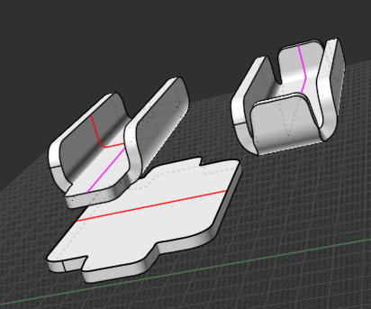
I extrude it to have a first solid. This solid is flat.

Next, I made the two red curves to do the flow by curves process.
for the non linear red curve, I made it with three lines joined.
I filleted the result and moved the points to have non symetrical fillet. This looks more realistic bending of metal.
With the first solid I flow it using the two red curves.
It gave me the second solid.

I use the same process to do a third solid using the second solid and the pink curves (curves made with the same method on the other axis)

I have redone it and I post the file here.

Attachments:

  Reply Reply More Options
Post Options
Reply as PM Reply as PM
Print Print
Mark as unread Mark as unread
Relationship Relationship
IP Logged

Previous
Next
 From:  Frenchy Pilou (PILOU)
10685.9 In reply to 10685.7 
Something like this ;) (sorry crossing posts)

  Reply Reply More Options
Post Options
Reply as PM Reply as PM
Print Print
Mark as unread Mark as unread
Relationship Relationship
IP Logged

Previous
 From:  mk (MARKY)
10685.10 
Thanks Phiro and Pilou,

Only now I noticed why I didn't see the Flow command work.
The new objects matched in those already made.
After I hid the 2nd and third solid I saw Flow command perfectly bending the source object.

Thanks again!
  Reply Reply More Options
Post Options
Reply as PM Reply as PM
Print Print
Mark as unread Mark as unread
Relationship Relationship
IP Logged
 

Reply to All Reply to All