How to create this contour form ?
 1-20  21

Next
 From:  Kwin
10161.1 
Hi
I am very new for MoI3D.
Anyone can guide me how to create this hill ?

I have tried loft , sweep , revolve rail, but all not work as I would like to do3
Loft can create surface but can follow the rail.
I attached this model file here as well.

Thank you very much


Image Attachments:
Size: 1.8 MB, Downloaded: 9 times, Dimensions: 2017x1870px
  Reply Reply More Options
Post Options
Reply as PM Reply as PM
Print Print
Mark as unread Mark as unread
Relationship Relationship
IP Logged

Previous
Next
 From:  bemfarmer
10161.2 In reply to 10161.1 
Hi Kwin,
Network does a fair job.
First convert the two stair stepped edges to curves.

- Brian
  Reply Reply More Options
Post Options
Reply as PM Reply as PM
Print Print
Mark as unread Mark as unread
Relationship Relationship
IP Logged

Previous
Next
 From:  Kwin
10161.3 In reply to 10161.2 
Hi Bran
Thank you for your quick reply.
I try network and it even worse.


  Reply Reply More Options
Post Options
Reply as PM Reply as PM
Print Print
Mark as unread Mark as unread
Relationship Relationship
IP Logged

Previous
Next
 From:  Michael Gibson
10161.4 In reply to 10161.1 
Hi Kwin, yes I think like Brian says Network is working well for this.

So to do that you would select these 4 curves:


Then run Construct > Network to make this result:


So one thing about Network though is that when you have the curves in one direction like this one:


Collapsing down to a single point up here:


It can help to get better shaping by having an intermediate curve to even out the shape before it squeezes down to a point, like this:


So then that will generate a result like this (3DM attached):


- Michael

  Reply Reply More Options
Post Options
Reply as PM Reply as PM
Print Print
Mark as unread Mark as unread
Relationship Relationship
IP Logged

Previous
Next
 From:  Michael Gibson
10161.5 In reply to 10161.3 
Hi Kwin, make sure you're not selecting these other curves when doing the Network:


Only select these ones:


The way Network works is it makes a surface out of a regular grid of curves. To make a regular grid there must be 2 directions of curves, kind of like a set of longitude and latitude lines on a globe. When you add those additional curves to the selection it can't form a sensible grid out of the batch of them and so you're getting a chaotic result there.

With just those 4 curves selected it forms a regular grid with one direction (like "latitude lines") like this:


And the other direction like longitude lines meeting in a "north pole" point like this:


That makes a proper 2 directional grid that can be networked. If you try to insert those other curves into the Network there isn't any proper latitude or longitude spot for them in the 2 directional grid that you need for Network.

- Michael

  Reply Reply More Options
Post Options
Reply as PM Reply as PM
Print Print
Mark as unread Mark as unread
Relationship Relationship
IP Logged

Previous
Next
 From:  Kwin
10161.6 
Hi Micheal

Many thanks for your clear answer. Now I can fix it.
(Sorry Brain, I should read your reply carefully)


I just have another question after create surface.
I would like to make it become solid in order to use Boolean operation.

I use planner tool to fill up open surface but some areas are not be filled.
How to check curve loop if planner is not work ?

Thanks again.
Image Attachments:
Size: 1.3 MB, Downloaded: 22 times, Dimensions: 3082x1471px
Size: 685.1 KB, Downloaded: 22 times, Dimensions: 1795x1389px
  Reply Reply More Options
Post Options
Reply as PM Reply as PM
Print Print
Mark as unread Mark as unread
Relationship Relationship
IP Logged

Previous
Next
 From:  ed (EDDYF)
10161.7 In reply to 10161.6 
To build on what Brian and Michael posted -

You just need to pick the green, red, orange & blue curves and perform Network.

If you want to turn this into a Solid, select 3 curves that make a plane and perform Planar. The example below shows making the bottom planar. Repeat Planar two more times for the sides.

Finally, select all the surfaces and Join. The result is a Solid.

Ed Ferguson

EDITED: 13 Feb 2021 by EDDYF

  Reply Reply More Options
Post Options
Reply as PM Reply as PM
Print Print
Mark as unread Mark as unread
Relationship Relationship
IP Logged

Previous
Next
 From:  Michael Gibson
10161.8 In reply to 10161.6 
Hi Kwin, to check if a curve is planar, get it joined together and then select it and click "Details..." . On the detailed object properties dialog that comes up it will show as "Planar" there:


But if you're not getting a result from Construct > Planar it means your curves are either not making a closed outline or are not planar.

- Michael
Attachments:

  Reply Reply More Options
Post Options
Reply as PM Reply as PM
Print Print
Mark as unread Mark as unread
Relationship Relationship
IP Logged

Previous
Next
 From:  Kwin
10161.9 
Thank you Micheal and Ed

It takes me a while to fill all surfaces. Finally I make it.
However after joint all 3 surfaces, it is not become solid. It shows as jointed surfaces.

Is anything wrong ?

Thanks again.


  Reply Reply More Options
Post Options
Reply as PM Reply as PM
Print Print
Mark as unread Mark as unread
Relationship Relationship
IP Logged

Previous
Next
 From:  Kwin
10161.10 In reply to 10161.9 
I am start to learn how to check problem.
From this image I count there are 6 edges but in Object properties window showing there are 8 edges.

Is it because of edges problem I can make this become single solid ?


  Reply Reply More Options
Post Options
Reply as PM Reply as PM
Print Print
Mark as unread Mark as unread
Relationship Relationship
IP Logged

Previous
Next
 From:  Kwin
10161.11 
Hi Michel

I can finally fix problem by adding small loop as your suggest.
but I still don't understand why without this arc, I can't create solid.
If you can explain a bit more about how to check edges error, .would be appreciated.

BTW, for newbie like me, I found this community is very supportive and really encourage me to move forward with MoI.

Thanks


  Reply Reply More Options
Post Options
Reply as PM Reply as PM
Print Print
Mark as unread Mark as unread
Relationship Relationship
IP Logged

Previous
Next
 From:  Michael Gibson
10161.12 In reply to 10161.11 
Hi Kwin,

re:
> but I still don't understand why without this arc, I can't create solid.

I would need to see the .3dm model file containing the problem object to be able to give you some more information on this part.

On the original file you posted above, "MoI Hill.3dm", you had 2 planar sides already built and I am able to do a network without the extra arc and then join those together and then seal off the bottom using Construct > Planar to make a solid.


That looks like a cool area for kids to use at school!

- Michael
  Reply Reply More Options
Post Options
Reply as PM Reply as PM
Print Print
Mark as unread Mark as unread
Relationship Relationship
IP Logged

Previous
Next
 From:  Frenchy Pilou (PILOU)
10161.13 
Revolve 90° on Rail don't makes the job ?

And you can Show Points and move them if you don't want a symetrical result!

@Michael : seems Caps End don't work! ??? So added by hand...

EDITED: 13 Feb 2021 by PILOU

  Reply Reply More Options
Post Options
Reply as PM Reply as PM
Print Print
Mark as unread Mark as unread
Relationship Relationship
IP Logged

Previous
Next
 From:  Michael Gibson
10161.14 In reply to 10161.13 
Hi Pilou,

re:
> Revolve 90° on Rail don't makes the job ?

It does, but the surface is a little more bumpy near the top than with the Network method I posted above. It also does not exactly match the original input which has slightly different shapes for the left and right side profiles.


> @Michael : seems Caps End don't work! ??? So added by hand...

Cap ends does not work with revolves for the case where a portion of the revolve profile is a line coincident with the revolve axis. Those coincident lines are removed before generating the revolve and then with that line missing there are not closed boundaries at the start and end to cap.

- Michael
  Reply Reply More Options
Post Options
Reply as PM Reply as PM
Print Print
Mark as unread Mark as unread
Relationship Relationship
IP Logged

Previous
Next
 From:  Frenchy Pilou (PILOU)
10161.15 In reply to 10161.14 
Thx for the explanations!
---
Pilou
Is beautiful that please without concept!
My Moi French Site My Gallery My MagicaVoxel Gallery
  Reply Reply More Options
Post Options
Reply as PM Reply as PM
Print Print
Mark as unread Mark as unread
Relationship Relationship
IP Logged

Previous
Next
 From:  WN
10161.16 In reply to 10161.6 
Hi Kwin.
From your file, I made a solid body, there is a video of this process at the link, if you are interested, you can watch it.

https://disk.yandex.ru/i/EF7lFPNW9xewag
Image Attachments:
Size: 367.8 KB, Downloaded: 7 times, Dimensions: 1907x1072px
  Reply Reply More Options
Post Options
Reply as PM Reply as PM
Print Print
Mark as unread Mark as unread
Relationship Relationship
IP Logged

Previous
Next
 From:  christian (CHRI)
10161.17 In reply to 10161.16 
Very clear vidéo

Thanks
  Reply Reply More Options
Post Options
Reply as PM Reply as PM
Print Print
Mark as unread Mark as unread
Relationship Relationship
IP Logged

Previous
Next
 From:  Kwin
10161.18 
Thank very everyone for helping.
I learn a lot faster from your replies.


@Micheal
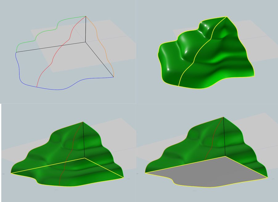
Actually my question should be how to read Object properties. (Above image)
When I can't create solid
Openjoint surface = 8 edges, 5 joined edges + 3 nake edges / 4 faces
Soild = 6 joined edges (no nake edges) / 4 faces

I think problem cause by surfaces are not closed because of some nake edges.
I redo this model again and can fix it.
If I clearly understand Object properties, next time I can check by myself.


Hi Pilou (Above image)
Thanks for suggesting rail revolve. It can be alternative way for create from like this.
Like Micheal answer, left and right profile are not the same but using this method I may tweak each profile later to make it different.


Hi WN (Above image)
Thanks a lot for very clear video.
I can get some small trick from you when I clearly see the whole process.

Cheers

  Reply Reply More Options
Post Options
Reply as PM Reply as PM
Print Print
Mark as unread Mark as unread
Relationship Relationship
IP Logged

Previous
Next
 From:  Frenchy Pilou (PILOU)
10161.19 
In general there are some possibilities for a same result! :)
---
Pilou
Is beautiful that please without concept!
My Moi French Site My Gallery My MagicaVoxel Gallery
  Reply Reply More Options
Post Options
Reply as PM Reply as PM
Print Print
Mark as unread Mark as unread
Relationship Relationship
IP Logged

Previous
Next
 From:  Frenchy Pilou (PILOU)
10161.20 
You can also consider SubDiv by Max Smirnov :)
http://moi3d.com/forum/index.php?webtag=MOI&msg=9689.1

Not exactly what do you want but...
Volume must be only external surfaces trimed without nothing inside!

EDITED: 16 Feb 2021 by PILOU

  Reply Reply More Options
Post Options
Reply as PM Reply as PM
Print Print
Mark as unread Mark as unread
Relationship Relationship
IP Logged
 

Reply to All Reply to All


Show messages:  1-20  21