STUMPED: tapered oval spoke
 1-20  21-23

Next
 From:  twofoot
10121.1 
Hi folks. I need to create a tapered oval spoke shape to complete this pattern for a steam train wheel pattern. See oval shapes with magenta arrows pointing to their respective positions.

Any suggestions? I cannot get it to form a solid that can be boolean unioned to create a single piece to send off to the foundry.

Thanks!

Chris

EDITED: 20 Feb 2022 by TWOFOOT

  Reply Reply More Options
Post Options
Reply as PM Reply as PM
Print Print
Mark as unread Mark as unread
Relationship Relationship
IP Logged

Previous
Next
 From:  Frenchy Pilou (PILOU)
10121.2 
Maybe you can make one by one
Then Boolean
Then Fillet the intersections

Here the first :)

EDITED: 21 Jan 2021 by PILOU

  Reply Reply More Options
Post Options
Reply as PM Reply as PM
Print Print
Mark as unread Mark as unread
Relationship Relationship
IP Logged

Previous
Next
 From:  bemfarmer
10121.3 In reply to 10121.1 
Hi twofoot,

In my opinion,
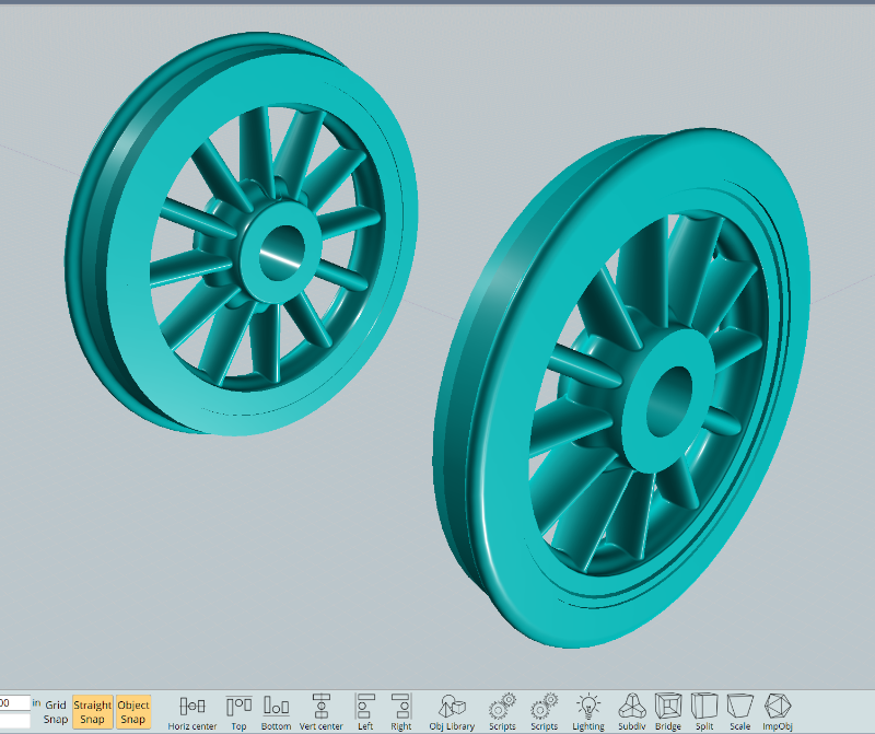
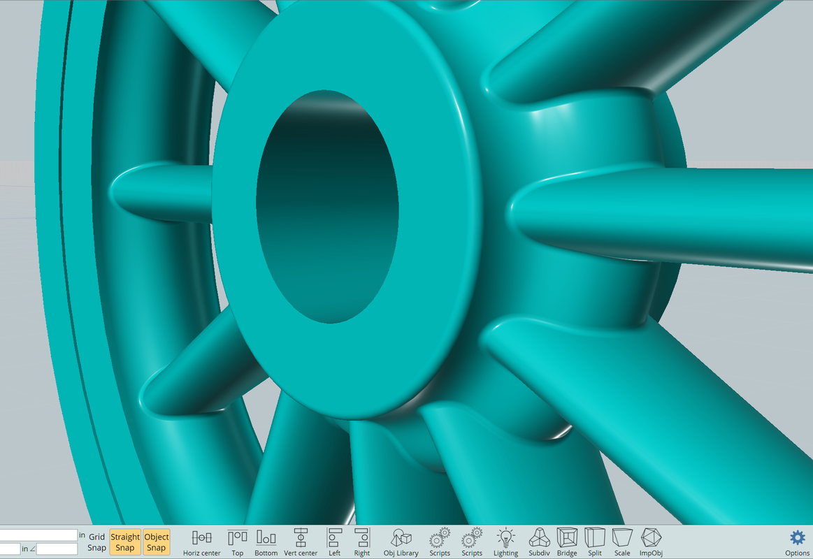
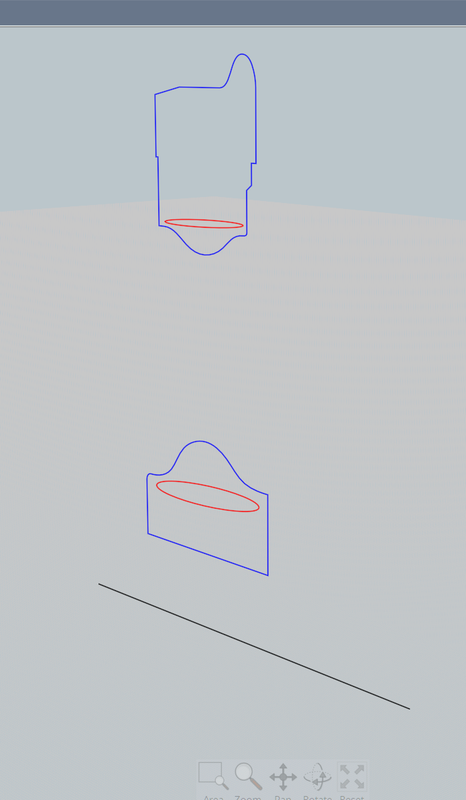
The two shapes pointed to are "Hubs", ("Rings"), for which each profile shown needs to be Revolved about the center point of the wheel.

The "spokes" are shown by the two angled, mostly straignt, curves, between the two Rings.
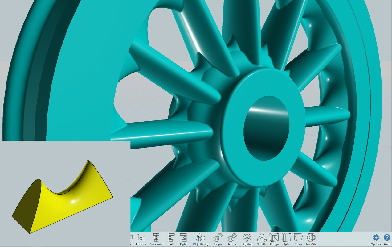
Their cross sections need to be shown.
Also, a view from the side of the wheel should be uploaded. It looks like there is such a view off to the left of your uploaded image.
Also, need to see the portion of the page below the uploaded image...

- Brian.

If the "spoke" is mostly solid, it may also need to be a Revolved solid, perhaps with pie sections cut away, per side view...

A google of "Train wheels images" shows different types of wheels. Perhaps you could upload an image of the corresponding type.

EDITED: 21 Jan 2021 by BEMFARMER

  Reply Reply More Options
Post Options
Reply as PM Reply as PM
Print Print
Mark as unread Mark as unread
Relationship Relationship
IP Logged

Previous
Next
 From:  bemfarmer
10121.4 In reply to 10121.1 
Hi twofoot,
Please post .3dm.
It is hard to understand what you are asking for...
- Brian
  Reply Reply More Options
Post Options
Reply as PM Reply as PM
Print Print
Mark as unread Mark as unread
Relationship Relationship
IP Logged

Previous
Next
 From:  Michael Gibson
10121.5 In reply to 10121.1 
Hi Chris, yes if you have a side or any other view image and if you could post the .3dm file with your current results in it that would help a lot to better understand what you're trying to do.

- Michael
  Reply Reply More Options
Post Options
Reply as PM Reply as PM
Print Print
Mark as unread Mark as unread
Relationship Relationship
IP Logged

Previous
Next
 From:  wayne hill (WAYNEHILL5202)
10121.6 In reply to 10121.1 
Hi Chris,

Is this the front truck wheels for a railroad train and tender? 999? In the Museum of Science and Industry, Chicago, IL ?

Wayne

https://www.albanyinstitute.org/tl_files/collection/historical-objects/1999.29_nycr-999.jpg

EDITED: 22 Jan 2021 by WAYNEHILL5202

  Reply Reply More Options
Post Options
Reply as PM Reply as PM
Print Print
Mark as unread Mark as unread
Relationship Relationship
IP Logged

Previous
Next
 From:  bemfarmer
10121.7 
There are a few other photos of this train.
The spokes appear to be a tapered, rounded, rectangular shape, wider from the center of the track to the outside of the track.
There would be some fillets as well.
Outside view would help establish their other dimensions seen from the side, and perhaps some of the fillets.
The inner and outer hubs, and the (10?) spokes, were likely cast in one piece.
I think that the outer rim, which contacts the track, would be designed to wear down, and be replaceable. (?)

Could not locate any plans on the web...

- Brian

William Buchanan was the designer of the "999."
40 inch tender wheels?
https://www.msichicago.org/explore/whats-here/exhibits/transportation-gallery/the-exhibit/999-steam-locomotive/

EDITED: 22 Jan 2021 by BEMFARMER

  Reply Reply More Options
Post Options
Reply as PM Reply as PM
Print Print
Mark as unread Mark as unread
Relationship Relationship
IP Logged

Previous
Next
 From:  ed (EDDYF)
10121.8 In reply to 10121.1 
Here is my attempt based on the blueprint and photos of the 999 engine I found on the web. These of course are the small truck wheels and not the large drive wheels.

The blueprint with just the one view is not enough information, but I hope I came close.

The original question was about getting the entire wheel to boolean into a solid. I had no issues with that, or with adding a fillet around the 12 spokes.

We would need to see your 3DM file to help out.

Ed Ferguson


Curves used to make the wheel:

  Reply Reply More Options
Post Options
Reply as PM Reply as PM
Print Print
Mark as unread Mark as unread
Relationship Relationship
IP Logged

Previous
Next
 From:  bemfarmer
10121.9 In reply to 10121.8 
Hi Ed,
Excellent work!
-Brian
  Reply Reply More Options
Post Options
Reply as PM Reply as PM
Print Print
Mark as unread Mark as unread
Relationship Relationship
IP Logged

Previous
Next
 From:  Anthony (PROP_DESIGN)
10121.10 In reply to 10121.8 
those shapes are quite beautiful ed.
  Reply Reply More Options
Post Options
Reply as PM Reply as PM
Print Print
Mark as unread Mark as unread
Relationship Relationship
IP Logged

Previous
Next
 From:  twofoot
10121.11 In reply to 10121.6 
Yes, it is for NYC 999.

Chris
  Reply Reply More Options
Post Options
Reply as PM Reply as PM
Print Print
Mark as unread Mark as unread
Relationship Relationship
IP Logged

Previous
Next
 From:  twofoot
10121.12 
Let me clarify. I sorted out my problem with the tapered spokes. Yay me. There never was a problem creating a single solid using booleans.

See screenshot. The red arrow points to an area where the fillets need to be very heavy *between* the spokes but not as heavy at the top and bottom of the spoke. I'm sure it's a blend or network or something else I also don't know how to use.

3dm file lives here for your viewing pleasure: https://www.dropbox.com/s/kkldadi27wf7y0t/NYC%20999%20tender%20wheel%20v2a.3dm?dl=0

Thanks

Chris

EDITED: 20 Feb 2022 by TWOFOOT

  Reply Reply More Options
Post Options
Reply as PM Reply as PM
Print Print
Mark as unread Mark as unread
Relationship Relationship
IP Logged

Previous
Next
 From:  bemfarmer
10121.13 In reply to 10121.12 
Hi Chris,
Very nice wheel.
May I ask where you found the "blueprints"?
Signed by Buchanan, they appear to be originals circa 1893, with some notes from 1919 and 1933.

Presumably when the 86" drive wheels we replaced with 70" wheels, the smaller wheels were changed also.
Spoke count must have changed also?

- Brian
  Reply Reply More Options
Post Options
Reply as PM Reply as PM
Print Print
Mark as unread Mark as unread
Relationship Relationship
IP Logged

Previous
Next
 From:  ed (EDDYF)
10121.14 In reply to 10121.12 
I looked at some photos on the Internet and there is definitely a web structure joining the spokes on each end. I think the way it all blends together will make it difficult for NURBs modeling - perhaps Sub D is the way to go on this one.

I attempted to make an approximation by creating filler pieces to go between the spokes. Maybe with some additional effort the filler pieces can be sized correctly and made such that they blend into the spokes more gracefully.

Ed Ferguson

  Reply Reply More Options
Post Options
Reply as PM Reply as PM
Print Print
Mark as unread Mark as unread
Relationship Relationship
IP Logged

Previous
Next
 From:  bemfarmer
10121.15 
Nice poster of the 999. (Original size wheels).

https://www.ebay.com/i/353260486381?chn=

Also found a beautiful scale model, but it only had 7 spokes.

- Brian
  Reply Reply More Options
Post Options
Reply as PM Reply as PM
Print Print
Mark as unread Mark as unread
Relationship Relationship
IP Logged

Previous
Next
 From:  Barry-H
10121.16 In reply to 10121.12 
Hi Chris,
perhaps this method may help.
After boolean union spokes to hub select the edge and join.
Add circles sized to the radii you need and sweep joined edge curve.
Trim Hub and blend.
Note when I produced the hub I rebuilt the curved section
so the surface was complete (no seam lines) this helps the blend operation.
Cheers
Barry


  Reply Reply More Options
Post Options
Reply as PM Reply as PM
Print Print
Mark as unread Mark as unread
Relationship Relationship
IP Logged

Previous
Next
 From:  twofoot
10121.17 In reply to 10121.16 
Barry, you are WAY better at Moi than I am. LOL

Is there any way you could show me the process step by step? This is EXACTLY what I need.

Thanks

Chris
  Reply Reply More Options
Post Options
Reply as PM Reply as PM
Print Print
Mark as unread Mark as unread
Relationship Relationship
IP Logged

Previous
Next
 From:  Barry-H
10121.18 In reply to 10121.17 
Hi Chris,
you can just use the fillet tool as shown in the photo.
I did the collar trim to give a variable fillet as I was unable to get it with the fillet tool.
I'm basically trimming the solid with a collar produced by sweeping desired fillets.
The sweep path is the edge where spoke joins the hub.
If your still unsure post me your curves and I will mark up what's needed.
Cheers
Barry

Edit:
It's possible to do it with the fillet tool with variable fillet my problem was filleting across the seam of the hub.


EDITED: 25 Jan 2021 by BARRY-H

Attachments:

  Reply Reply More Options
Post Options
Reply as PM Reply as PM
Print Print
Mark as unread Mark as unread
Relationship Relationship
IP Logged

Previous
Next
 From:  Finema
10121.19 In reply to 10121.18 
Hi
have you try ONSHAPE to do the bevel ?
  Reply Reply More Options
Post Options
Reply as PM Reply as PM
Print Print
Mark as unread Mark as unread
Relationship Relationship
IP Logged

Previous
Next
 From:  DanC
10121.20 
@ Barry-H, how did you get the sweeped circles to meet the spokes and hub at a tangent with your first technique? Or are they just roughly positioned close enough to tangential to suffice?
  Reply Reply More Options
Post Options
Reply as PM Reply as PM
Print Print
Mark as unread Mark as unread
Relationship Relationship
IP Logged
 

Reply to All Reply to All


Show messages:  1-20  21-23