Ship hull tutorials
 1-3  …  24-43  44-63  64-83  84-103  104-123  124-129

Previous
Next
 From:  corchet
9819.64 


a small gap on your last try posted in 3dm


here another way ... easy to do ... loft between curves

with cap end ... the result is solid

you can easily build a second piece and boolean diff to obtain a hull with various width

( the yellow line is a guide to align the profiles ... not necessary in the Loft command )

and as usual .. better results with profiles cleaned with Rebuild ;)

model joined ... à toutes fins utiles

EDITED: 9 Sep 2020 by CORCHET

  Reply Reply More Options
Post Options
Reply as PM Reply as PM
Print Print
Mark as unread Mark as unread
Relationship Relationship
IP Logged

Previous
Next
 From:  Frenchy Pilou (PILOU)
9819.65 
@ Corchet : Les gondoles à Venise! Excellentissismo! :)

And always the tricky function MoveSliceToPoint by Michael from an existing document
where you redraw the curves! The best and easy way!
http://moi3d.com/forum/messages.php?webtag=MOI&msg=2749.36


else!

EDITED: 4 Jun 2020 by PILOU

  Reply Reply More Options
Post Options
Reply as PM Reply as PM
Print Print
Mark as unread Mark as unread
Relationship Relationship
IP Logged

Previous
Next
 From:  corchet
9819.66 In reply to 9819.65 
yes ;)
  Reply Reply More Options
Post Options
Reply as PM Reply as PM
Print Print
Mark as unread Mark as unread
Relationship Relationship
IP Logged

Previous
Next
 From:  corchet
9819.67 


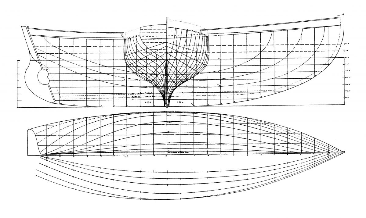
something easy to modify to change the general shape of the " noix de coco " ;) mixture of 2 lofts and 2 networks

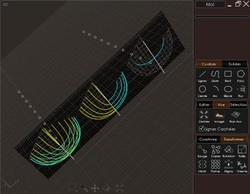
1 - 4 lines to loft on each side give only 2 pieces

2 - select the 2 pieces and copy paste

3 - 4 - in the top view draw a line as closest as possible of the middle of the hull ( to prevent join problem ... it's better to do that )

4 - boolean diff to cut the half hull

5 - mirror to obtain 2 perfectly joined pieces

6 - draw a line as show on the pict

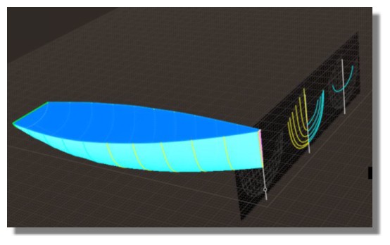
7 - before apply network to cap the hull ... join to verify it is closed curved - separate and rejoin the neccessary parts of the border - be sure to have the 3 parts ( in yellow )

8 ' select the four pieces ( 2 caps and 2 hull ) and join ... it's a solid

9 - with only small modfications of the curves in top or left axis ... it's easy to change the general shape of the boat

and possible to add other curves on Z axe to refine the shape for various borders etc ...

EDITED: 9 Sep 2020 by CORCHET

  Reply Reply More Options
Post Options
Reply as PM Reply as PM
Print Print
Mark as unread Mark as unread
Relationship Relationship
IP Logged

Previous
Next
 From:  corchet
9819.68 


et qqs booleans plus tard

EDITED: 9 Sep 2020 by CORCHET

  Reply Reply More Options
Post Options
Reply as PM Reply as PM
Print Print
Mark as unread Mark as unread
Relationship Relationship
IP Logged

Previous
Next
 From:  corchet
9819.69 


adding profiles for a round top
adding profiles with scales to loft the internal hull ( yellow )

EDITED: 9 Sep 2020 by CORCHET

  Reply Reply More Options
Post Options
Reply as PM Reply as PM
Print Print
Mark as unread Mark as unread
Relationship Relationship
IP Logged

Previous
Next
 From:  Gord (NEOMEGA)
9819.70 
Thanks guys - finally did it somehow!
Image Attachments:
Size: 425.8 KB, Downloaded: 38 times, Dimensions: 1958x688px
Size: 1.1 MB, Downloaded: 34 times, Dimensions: 1414x1358px
Size: 1.8 MB, Downloaded: 37 times, Dimensions: 2012x1406px
  Reply Reply More Options
Post Options
Reply as PM Reply as PM
Print Print
Mark as unread Mark as unread
Relationship Relationship
IP Logged

Previous
Next
 From:  Michael Gibson
9819.71 In reply to 9819.70 
That's great Gord!

- Michael
  Reply Reply More Options
Post Options
Reply as PM Reply as PM
Print Print
Mark as unread Mark as unread
Relationship Relationship
IP Logged

Previous
Next
 From:  Frenchy Pilou (PILOU)
9819.72 
@ Corchet What a diversity of variable floating conception! :)

@ Gord Cool result!
---
Pilou
Is beautiful that please without concept!
My Moi French Site My Gallery My MagicaVoxel Gallery
  Reply Reply More Options
Post Options
Reply as PM Reply as PM
Print Print
Mark as unread Mark as unread
Relationship Relationship
IP Logged

Previous
Next
 From:  Frenchy Pilou (PILOU)
9819.73 
Else...;)

---
Pilou
Is beautiful that please without concept!
My Moi French Site My Gallery My MagicaVoxel Gallery
  Reply Reply More Options
Post Options
Reply as PM Reply as PM
Print Print
Mark as unread Mark as unread
Relationship Relationship
IP Logged

Previous
Next
 From:  Gord (NEOMEGA)
9819.74 In reply to 9819.73 
Thanks! Really interesting!

G
  Reply Reply More Options
Post Options
Reply as PM Reply as PM
Print Print
Mark as unread Mark as unread
Relationship Relationship
IP Logged

Previous
Next
 From:  Gord (NEOMEGA)
9819.75 In reply to 9819.73 
OK, another issue on my next project. I'm doing a Clyde Puffer. I have the hull done and in solids. Yes, I know it could be fairer, but whatever, the master model can be sanded slightly, and these things had lumps everywhere!

I have 3 solids, but try as I might, I cannot get the two stern ones to boolean into the others. I tried Diff and Union, but no result. Why won't it do this. I can cut a line through the sterns, but I can't use this technique to trim off the ends to be flush for some reason. Nothing works again!

Thanks!

Gord.

EDITED: 26 Jun 2020 by NEOMEGA

Image Attachments:
Size: 1.8 MB, Downloaded: 36 times, Dimensions: 2038x1536px
  Reply Reply More Options
Post Options
Reply as PM Reply as PM
Print Print
Mark as unread Mark as unread
Relationship Relationship
IP Logged

Previous
Next
 From:  Michael Gibson
9819.76 In reply to 9819.75 
Hi Gord, it's the bottom curved surface of the stern pieces. There are damaged trimming boundaries in these spots:


And there's a kind of mutated micro shelf in this area:


How did you create this piece, was it a result of a Shell operation? It kind of looks like the sort of stuff that Shell messes up on.

It's also possible that this very thin area here could be considered an area of self intersection:


It's not generally good to have opposite sides of a solid squish down to such a thin area.

If you have any earlier stages of these pieces if you can post them I might be able to tell you where things started to go wrong with them.

- Michael

  Reply Reply More Options
Post Options
Reply as PM Reply as PM
Print Print
Mark as unread Mark as unread
Relationship Relationship
IP Logged

Previous
Next
 From:  Frenchy Pilou (PILOU)
9819.77 In reply to 9819.74 
Yep this serial of videos is very instructive how is made a wood boat! !
(i am on 20/73...; )

And Albert Strange a cool artist and Yacht designer!
https://en.wikipedia.org/wiki/Albert_Strange

Hull Plan of Tally Ho from another cool site : https://davestallyhomodel.blogspot.com/2019/02/the-first-steps.html


Amazing stuff!

EDITED: 9 Jun 2020 by PILOU

  Reply Reply More Options
Post Options
Reply as PM Reply as PM
Print Print
Mark as unread Mark as unread
Relationship Relationship
IP Logged

Previous
Next
 From:  Gord (NEOMEGA)
9819.78 In reply to 9819.76 
Thanks. Yes, it was network surface then boolean joined. It's not repairable then? I know I'm doing a difficult shame again as one part has to go down to basically nothing, whilst the other upper part has to be 90 deg. to it. Not sure what to do now. It is OK on loft, but it doesn't follow the plan shape too accurately though.

EDITED: 26 Jun 2020 by NEOMEGA

Image Attachments:
Size: 1.3 MB, Downloaded: 27 times, Dimensions: 1788x996px
  Reply Reply More Options
Post Options
Reply as PM Reply as PM
Print Print
Mark as unread Mark as unread
Relationship Relationship
IP Logged

Previous
Next
 From:  Frenchy Pilou (PILOU)
9819.79 In reply to 9819.78 
Maybe you can see the videos about hulls about this site (and free prog ;)
(not so easy than moi! ;)
http://www.polycad.co.uk
---
Pilou
Is beautiful that please without concept!
My Moi French Site My Gallery My MagicaVoxel Gallery
  Reply Reply More Options
Post Options
Reply as PM Reply as PM
Print Print
Mark as unread Mark as unread
Relationship Relationship
IP Logged

Previous
Next
 From:  Michael Gibson
9819.80 In reply to 9819.78 
Hi Gord,

re:
> Yes, it was network surface then boolean joined.

It looks like there are just a couple of spots where the endpoints don't touch. It would probably be a good idea after you construct one of these networks that you want to join to other straight parts, to edit surface control points and ensure the end control points are all trued up to be flat so the ends will be planar.

It's probably things waving around just a little bit out of being planar that is causing enough misalignment to be problematic.


> It's not repairable then?

It might be, I'll take a crack at it.

- Michael
  Reply Reply More Options
Post Options
Reply as PM Reply as PM
Print Print
Mark as unread Mark as unread
Relationship Relationship
IP Logged

Previous
Next
 From:  Gord (NEOMEGA)
9819.81 In reply to 9819.80 
Appreciate it, thanks!

Is there a scrip I can run to allow me to see these problem areas highlighted larger? I use N, but it only shows the whole edge.

G
  Reply Reply More Options
Post Options
Reply as PM Reply as PM
Print Print
Mark as unread Mark as unread
Relationship Relationship
IP Logged

Previous
Next
 From:  Michael Gibson
9819.82 In reply to 9819.81 
Hi Gord, there isn't any script for that, you just zoom in closely especially on corner areas where things join up. You can use the "Zoom area" tool to zoom in centered on a specific spot.

- Michael
  Reply Reply More Options
Post Options
Reply as PM Reply as PM
Print Print
Mark as unread Mark as unread
Relationship Relationship
IP Logged

Previous
Next
 From:  Michael Gibson
9819.83 In reply to 9819.81 
Hi Gord, here is a stern piece which should be all trued up. I think this could use it here too though:


- Michael

  Reply Reply More Options
Post Options
Reply as PM Reply as PM
Print Print
Mark as unread Mark as unread
Relationship Relationship
IP Logged
 

Reply to All Reply to All


Show messages:  1-3  4-23  24-43  44-63  64-83  84-103  104-123  124-129