V4 beta Jan-22-2020 available now
 1-2  3-22  23-42  43-62  63-82  83-102  …  163-178

Previous
Next
 From:  nemuneko
9660.43 In reply to 9660.42 
Hi Michael,

>That was for English/Number, Kana, and CapsLock keys, is that correct?

Yes.

>The English/Number and Kana keys are modifier/mode type keys is that correct? I mean they don't produce a printable character if you press it just by itself?
Yes, they are special mode keys which used to switch input methods (English <-> Japanese). They don't produce a printable character.
Also I think English/Number and Kana keys are not used for shortcut.
(I add them to the symptom list just to cover all physical key behaviors. I'm sorry if you recognize these keys are modifier key used for shortcut.)

Thanks.

nemuneko
  Reply Reply More Options
Post Options
Reply as PM Reply as PM
Print Print
Mark as unread Mark as unread
Relationship Relationship
IP Logged

Previous
Next
 From:  Michael Gibson
9660.44 In reply to 9660.43 
Thanks nemuneko, I thought it was like that but I wanted to double check to make sure.

Thanks, - Michael
  Reply Reply More Options
Post Options
Reply as PM Reply as PM
Print Print
Mark as unread Mark as unread
Relationship Relationship
IP Logged

Previous
Next
 From:  Marc (TELLIER)
9660.45 
Hi,

I guess this has been mentioned, the fractional display on the dimensions does not work.

Otherwise I like the behaviour of dimensions, maybe the could be a stop on the resizing of the text when you zoom out at a certain point (perhaps when the text touches the arrows?).

Thanks,

Marc
  Reply Reply More Options
Post Options
Reply as PM Reply as PM
Print Print
Mark as unread Mark as unread
Relationship Relationship
IP Logged

Previous
Next
 From:  Michael Gibson
9660.46 In reply to 9660.45 
Hi Marc,

re:
> I guess this has been mentioned, the fractional display on the dimensions does not work.

Fractional display should be working if you set Formatting > Distance display > Feet & Inches, but you also need the current unit system (under Options > General > Units) to something other than "No unit system" for it to take effect.

If you have "No unit system" then it isn't able to determine how long a foot is so "feet & inches" type fractional display isn't able to work there.


> Otherwise I like the behaviour of dimensions, maybe the could be a stop on the
> resizing of the text when you zoom out at a certain point (perhaps when the text
> touches the arrows?).

Well there isn't actually any resizing of text currently. Right now text is always drawn at the same on-screen point size regardless of zoom. This does have a kind of sense that it is sizing when you zoom out and objects become smaller but text size remains the same.

I do want to experiment in the future with some options to shrink the text down when you zoom out. But doing it when the text touches arrows would result in a variety of different text sizes on different dimensions if some have plenty of room between the arrows and others do not. The other problem is that text blocks only have a single reference point and so there is no "in between" measurement to use for them.

It will probably need to be a setting for "Max text size in model units" or something like that so you could say make stuff smaller than 5 model units to be shrunk down. That's probably not going to happen for the v4 timeframe. But there is one more related area that I have left to work on for v4 which is an option to make the text size entirely controlled by model size so it both shrinks and grows in size when zoomed same as geometry does. One part that's not good about that is that it then can cause really large sized text. But that way will have better compatibility with how other CAD programs handle text.

Thanks,
- Michael
  Reply Reply More Options
Post Options
Reply as PM Reply as PM
Print Print
Mark as unread Mark as unread
Relationship Relationship
IP Logged

Previous
Next
 From:  Yanik
9660.47 
Dear Michael,

I have some DXF file that can't be offsetted properly. I'm trying to generate roads from curves I imported. I'm using the offset tool using the Bidirectional and Trim settings with a distance of 0,15. The curves get disconnected.

I hope you can take a look at it. I've attached the .dxf as an attachment.
Attachments:

  Reply Reply More Options
Post Options
Reply as PM Reply as PM
Print Print
Mark as unread Mark as unread
Relationship Relationship
IP Logged

Previous
Next
 From:  Michael Gibson
9660.48 In reply to 9660.47 
Hi Yanik, re: offset problem - I think the problem is that Offset in MoI is focused on working on a closed loop, not a branching structure like you have here.

It will try to join together segments that touch to try and make a closed loop but that is not good for your branching structure.

I don't think that MoI's offset will produce the kind of result you're looking for here, you've got not just branching but some pieces touching others in spots other than endpoints making "T" junctures. MoI's curve offset is not set up to handle those either.

Maybe a 2D CAD program that has an architectural type "wall" offset might do what you are looking for.

- Michael
  Reply Reply More Options
Post Options
Reply as PM Reply as PM
Print Print
Mark as unread Mark as unread
Relationship Relationship
IP Logged

Previous
Next
 From:  Michael Gibson
9660.49 In reply to 9660.47 
Hi Yanik, you might be able to get somewhere with that with Max Smirnov's "Fatlines" script (http://moi.maxsm.net/files/), I think that script will thicken each curve individually instead of trying to join things together to make closed loops like MoI's regular offset function does.

- Michael
  Reply Reply More Options
Post Options
Reply as PM Reply as PM
Print Print
Mark as unread Mark as unread
Relationship Relationship
IP Logged

Previous
Next
 From:  Frenchy Pilou (PILOU)
9660.50 
Funny that i adviced somewhere ;)

Seems you must trim in some parts before use Fat Lines
Don't know if there too many roads or if there are particular intersections or ...
red = trimming polylines

EDITED: 24 Feb 2020 by PILOU

  Reply Reply More Options
Post Options
Reply as PM Reply as PM
Print Print
Mark as unread Mark as unread
Relationship Relationship
IP Logged

Previous
Next
 From:  Yanik
9660.51 In reply to 9660.48 
Hi Michael the lines are all individual lines. Each road is a polyline with multiple points. The concave points have issues when offsetting them. The FatLines script has the same issues.
Not sure what the problem is. It works fine on similar drawn polylines.
  Reply Reply More Options
Post Options
Reply as PM Reply as PM
Print Print
Mark as unread Mark as unread
Relationship Relationship
IP Logged

Previous
Next
 From:  nameless
9660.52 In reply to 9660.51 
Having used FatLines script in complex senarios (recent one was a vitro window for a 3d scene) it helps to separate the project in portions. When I tried to apply it at once to all of the linework things froze up.
  Reply Reply More Options
Post Options
Reply as PM Reply as PM
Print Print
Mark as unread Mark as unread
Relationship Relationship
IP Logged

Previous
Next
 From:  Yanik
9660.53 
If I offset just 1 polyline I get the same issues. So it's not related to complexity. Try the dxf and you'll see.
  Reply Reply More Options
Post Options
Reply as PM Reply as PM
Print Print
Mark as unread Mark as unread
Relationship Relationship
IP Logged

Previous
Next
 From:  Michael Gibson
9660.54 In reply to 9660.53 
Hi Yanik,

re:
> If I offset just 1 polyline I get the same issues. So it's not related to complexity. Try the dxf and you'll see.

I am seeing some issues with polylines that are at shallow angles to one another.

In general MoI is not expecting to work with polylines like that which have numerous line segments at shallow angles to one another, it's expecting for things shaped like that to be smooth curves and not polylines.

- Michael
  Reply Reply More Options
Post Options
Reply as PM Reply as PM
Print Print
Mark as unread Mark as unread
Relationship Relationship
IP Logged

Previous
Next
 From:  Marc (TELLIER)
9660.55 In reply to 9660.46 
Hi Michael,

I'm not sure I understand, shouldn't the dimension display units be independent of the model's?
Hobbit's foot are something else than 12 inches? :)

Marc
  Reply Reply More Options
Post Options
Reply as PM Reply as PM
Print Print
Mark as unread Mark as unread
Relationship Relationship
IP Logged

Previous
Next
 From:  Frenchy Pilou (PILOU)
9660.56 In reply to 9660.54 
This curious thing of looping was due of an old version of Fatlines!


with the FatLines for v4 no more looping! : even with the DXF above post! ;)
Lignes Epaisses = FatLines

EDITED: 24 Feb 2020 by PILOU

  Reply Reply More Options
Post Options
Reply as PM Reply as PM
Print Print
Mark as unread Mark as unread
Relationship Relationship
IP Logged

Previous
Next
 From:  BurrMan
9660.57 In reply to 9660.53 
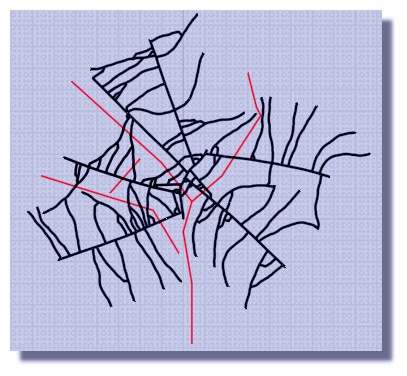
Here is a result I made. 3 or 4 lines are missing, but it could have been dealt with. A little more than just 1 click though.


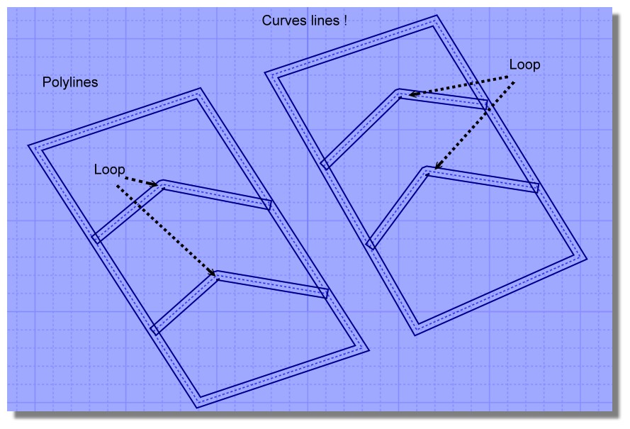
Since you want to keep the breakpoints of the polylines, that is what kindof makes the offsetting hard.

So I joined and rebuilt the original file (Rebuild to remove all the corner points)

Then I extruded the new curves and shelled them on centerline. I could then Boolean together the shelled solids into a single solid.
(This is where I lost 4 lines. they would need to be addressed at the extrusion level to get good solids to bool)

From the single solid, I can extract the bottom edges to create the thickened curves.

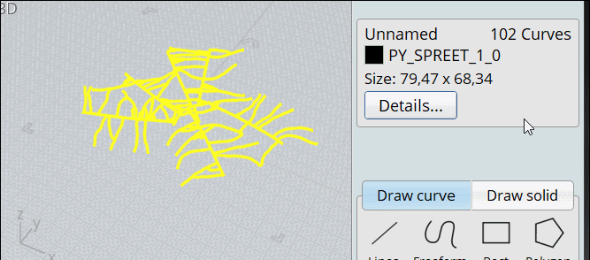
I can now bring in the original file and extract the points I wanted to keep (As waypoints I guess?)

Anyway, I can make a video if this file looks like what you are after and you wanted to see more.

EDITED: 27 Nov 2020 by BURRMAN

Attachments:

  Reply Reply More Options
Post Options
Reply as PM Reply as PM
Print Print
Mark as unread Mark as unread
Relationship Relationship
IP Logged

Previous
Next
 From:  Frenchy Pilou (PILOU)
9660.58 
The curious is the FatLines works fine with only certain measures of lines...
---
Pilou
Is beautiful that please without concept!
My Moi French Site My Gallery My MagicaVoxel Gallery
  Reply Reply More Options
Post Options
Reply as PM Reply as PM
Print Print
Mark as unread Mark as unread
Relationship Relationship
IP Logged

Previous
Next
 From:  Andre
9660.59 
Not sure if rendering bug or performance optimization:

  Reply Reply More Options
Post Options
Reply as PM Reply as PM
Print Print
Mark as unread Mark as unread
Relationship Relationship
IP Logged

Previous
Next
 From:  Michael Gibson
9660.60 In reply to 9660.59 
Hi Andre, it's kind of both. It's a known rendering bug but it has intentionally not been fixed as of yet since the fix could cause some performance degradation for all curve drawing.

See here:
http://moi3d.com/forum/index.php?webtag=MOI&msg=4101.2

At some point I should be able to do a careful fix but I'm not sure exactly when. Thanks for reporting it.

- Michael
  Reply Reply More Options
Post Options
Reply as PM Reply as PM
Print Print
Mark as unread Mark as unread
Relationship Relationship
IP Logged

Previous
Next
 From:  AlexPolo
9660.61 
HI Michael,

Really enjoying the DIMS function in MOI great for quick markups. Here is one example if possible to add a dimension style where the dimension sits outside to the side of the lines dimensioned area. In areas where mixing large scale and small scale dimensions would be good so its still legible.


EDITED: 20 Sep 2020 by ALEXPOLO

Attachments:

  Reply Reply More Options
Post Options
Reply as PM Reply as PM
Print Print
Mark as unread Mark as unread
Relationship Relationship
IP Logged

Previous
Next
 From:  Michael Gibson
9660.62 In reply to 9660.61 
Hi Alex, in the Jan-22-2020 v4 beta there is now an option for putting the arrows to the outside like you want there.

It's under Arrows > Position = "Outside" , and also when it is set some additional options for "Outside line length" and "Draw line across" will appear in the "Dim lines" section:


It does not try to place the text to the outside but (it looks like you've seen this already) you can turn on edit points for a dim with Edit > Show pts and then drag the point for the text to position it off to the side where you want it.

You can set Arrows > Position = "Outside" on an individual dimension by using the "Details..." button in the object properties that shows up for the selected object, or also set it as a preset under Options > Dimensions, then select that preset when you initially draw the dimension.

Let me know if that was not what you were looking for.

- Michael

  Reply Reply More Options
Post Options
Reply as PM Reply as PM
Print Print
Mark as unread Mark as unread
Relationship Relationship
IP Logged
 

Reply to All Reply to All


Show messages:  1-2  3-22  23-42  43-62  63-82  83-102  103-122  …  163-178