MoI tutorials
 1-8  9-26

Previous
Next
 From:  Frenchy Pilou (PILOU)
9508.9 
<< I don`t want to ask every time
Why not : there is always something to learn for you and for us! :)
  Reply Reply More Options
Post Options
Reply as PM Reply as PM
Print Print
Mark as unread Mark as unread
Relationship Relationship
IP Logged

Previous
Next
 From:  mdesign
9508.10 In reply to 9508.8 
Thanks. I`ve done it only with blends (delete short curves on corners and do blend there). Fillets are ok.

How did you know that there is a problem? High density of dots? Jagged line (not smooth)?
  Reply Reply More Options
Post Options
Reply as PM Reply as PM
Print Print
Mark as unread Mark as unread
Relationship Relationship
IP Logged

Previous
Next
 From:  Michael Gibson
9508.11 In reply to 9508.7 
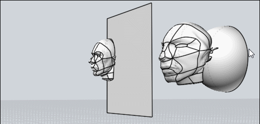
Hi Bartosh, so part of the overall strategy of constructing things from 2D profile curves is avoiding poor quality curves. The quality of the curves will often inherit into the 3D model structure built from them and if you have junky curves that will yield junky models.

The quality of curves coming from a 2D illustration program can often times be pretty bad. 2D illustration work can tolerate lower quality curves because they don't do as complex calculations on them as is required for filleting.

So in your case here seeing the low quality of the curves you would want to draw new ones in Moi just using the ones from the file as a reference point and then throwing them out.


> 1) I`ve noticed red squares. I can`t find what it means? I`ve deleted it and filled gaps with new curves.

Like Pilou wrote above, this indicates multiple control points from a single curve segment stacked up right on top of each other. This degrades some of the mathematical properties of the curve and should be avoided.


> 2) I`ve unjoined curve to fix it (it was build from many short curves). I`ve tried merge
> command. I`ve tried rebuild command. Without success.

Well with curves as messy as these to get best results I would recommend throwing them away and drawing new ones. You can snap a couple of points onto them to guide your new curves like I'd probably start by drawing in a few lines for the straight areas.


> 3) I`ve joined those curves once again. Tried extrude on it. All works fine. I`ve seen those short edges and I knew that will be problem with that.

Extrude is less sensitive to curve quality than filleting.


> 4) error :)

Yup, messy curves will make for errors down the road with more complex calculations. You want to start out with good quality curves to avoid that from happening.

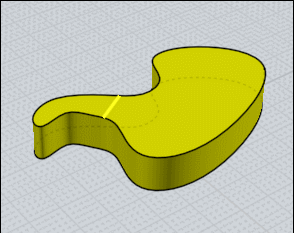
A couple of the problem areas of these curves is the stacked up control points like you noticed but it's also split up into numerous small segments which are not smooth to each other, for example here is one spot that you can see is a line segment not smoothly connected to its neighboring segments:


- Michael

  Reply Reply More Options
Post Options
Reply as PM Reply as PM
Print Print
Mark as unread Mark as unread
Relationship Relationship
IP Logged

Previous
Next
 From:  Frenchy Pilou (PILOU)
9508.12 In reply to 9508.10 
Don't forget that in Nurbs Points are just "Control points" so when you see many points on or around a curve that is a not efficient use of them! ;)

And a fillet in Moi3D is the maximum of the less admissible arc/width on the path perimeter of a selection !

EDITED: 1 Oct 2019 by PILOU

  Reply Reply More Options
Post Options
Reply as PM Reply as PM
Print Print
Mark as unread Mark as unread
Relationship Relationship
IP Logged

Previous
Next
 From:  Michael Gibson
9508.13 In reply to 9508.10 
Hi Bartosh,

re:
> How did you know that there is a problem? High density of dots? Jagged line (not smooth)?

Well, just zooming in on the top view I can see areas where the curve is not smooth like shown in the above screenshots.

If the curve was all smooth you wouldn't have so many little faces in your extrusion like you have here:


- Michael
Attachments:

  Reply Reply More Options
Post Options
Reply as PM Reply as PM
Print Print
Mark as unread Mark as unread
Relationship Relationship
IP Logged

Previous
Next
 From:  mdesign
9508.14 
Thanks for help.

@Micheal: You`ve replied in some forum thread that ViaCAD has got better filleting engine. Should I understood it that I should buy this soft ass addition for MoI and I won`t be forced to fixed jagged line like this? Do you still hold your statement about quality of ViaCAD fillet engine? Is this same with blending?
  Reply Reply More Options
Post Options
Reply as PM Reply as PM
Print Print
Mark as unread Mark as unread
Relationship Relationship
IP Logged

Previous
Next
 From:  Frenchy Pilou (PILOU)
9508.15 
About the fillet maxi impossible above to overpass in one shoot just Boolean Diff your object and make a variable Fillet on the other part! (on its own limits of course) ;)
Boolean union at the end if necessary...

So on the second part make a general fillet at the maxi of the first part
Then create your Variable fillet as you want with any variation admissible!

Here only one > 1
3 for example somewhere on the perimeter :)

EDITED: 1 Oct 2019 by PILOU

  Reply Reply More Options
Post Options
Reply as PM Reply as PM
Print Print
Mark as unread Mark as unread
Relationship Relationship
IP Logged

Previous
Next
 From:  mdesign
9508.16 
Is it possible to do some deformation gradually in MoI like Modo ones with linear falloffs?


Is it possible in MoI to align curve points linear to get straight line without deleting points?

  Reply Reply More Options
Post Options
Reply as PM Reply as PM
Print Print
Mark as unread Mark as unread
Relationship Relationship
IP Logged

Previous
Next
 From:  mdesign
9508.17 In reply to 9508.15 
Wow. This blown my head out :)
  Reply Reply More Options
Post Options
Reply as PM Reply as PM
Print Print
Mark as unread Mark as unread
Relationship Relationship
IP Logged

Previous
Next
 From:  mdesign
9508.18 In reply to 9508.15 
How have you done that second part with fillet with two radius values?

Attachments:

  Reply Reply More Options
Post Options
Reply as PM Reply as PM
Print Print
Mark as unread Mark as unread
Relationship Relationship
IP Logged

Previous
Next
 From:  Frenchy Pilou (PILOU)
9508.19 In reply to 9508.18 
If you want several specific values you must make a another Set of fillet for each value! ;)

So a general value with the previous maximum value of the first part so 1 unity

then

set 1 value 2.3
set 2 value 3
set 3 value 5
etc

but just one make a smoothy transition like in my example above! ;)
  Reply Reply More Options
Post Options
Reply as PM Reply as PM
Print Print
Mark as unread Mark as unread
Relationship Relationship
IP Logged

Previous
Next
 From:  Frenchy Pilou (PILOU)
9508.20 
About your Falloff

maybe this but that works only on one delimited surface at a time!

  Reply Reply More Options
Post Options
Reply as PM Reply as PM
Print Print
Mark as unread Mark as unread
Relationship Relationship
IP Logged

Previous
Next
 From:  Frenchy Pilou (PILOU)
9508.21 
FallOff again : a little tricky but easy ! ;)

Separate your surface (then move it (not obliged) or inverse selection more easy for see something)
Use the ShrinkTrimmedSrf hidden function for restric the aera of control point to your rectangle surface
(Michael will explain that some better than me:)

For use it make a simple shortcut with ShrinkTrimmedSrf on the second column or Press tab and copy/past this curious words from anywhere you want :)


Add Control Points (any as you want)
Move them as you want

Boolean Union to the original (not made follow but easy ;)

Et voilĂ ! :)


and don't forget: Control Points in Nurbs are absolutly not the same than Points in Polygon Modeler than Modo or other!
They can be overlapped to a curve when you make a Rebuild for example but as soon as you modify something they are not more on it! :)

There surrely in the futur a deformation box but...only Michael can be more precise :)

You can also deform your nurbs volume by the native Flow Function!
= Deform volume by another volume!

say this one


no problem for deform it by any volume! :)
not refound the old man but it will be the same!

EDITED: 1 Oct 2019 by PILOU

  Reply Reply More Options
Post Options
Reply as PM Reply as PM
Print Print
Mark as unread Mark as unread
Relationship Relationship
IP Logged

Previous
Next
 From:  Michael Gibson
9508.22 In reply to 9508.14 
Hi Bartosh,

re:
> @Micheal: You`ve replied in some forum thread that ViaCAD has got better filleting engine. Should I understood
> it that I should buy this soft ass addition for MoI and I won`t be forced to fixed jagged line like this? Do you still
> hold your statement about quality of ViaCAD fillet engine?

Definitely ViaCAD's fillet engine is much better than MoI's but it is not likely to be able to fillet a messy object like that either. Filleting in CAD is just too complex of an operation and it is more designed around having accurate geometry to work with not messy geometry.

I tested your particular file in the old version of ViaCAD I have here and it gives this error:


re:
> Is this same with blending?

I don't think ViaCAD has a surface blend function like MoI's.

- Michael

  Reply Reply More Options
Post Options
Reply as PM Reply as PM
Print Print
Mark as unread Mark as unread
Relationship Relationship
IP Logged

Previous
Next
 From:  Michael Gibson
9508.23 In reply to 9508.16 
Hi Bartosh,

re:
> Is it possible to do some deformation gradually in MoI like Modo ones with linear falloffs?

Not really, no - if you need that kind of deformation you would probably want to use a polygon modeler for that project rather than a CAD program.


> Is it possible in MoI to align curve points linear to get straight line without deleting points?

You can use the Transform > Align command to make a set of points lined up in a vertical or horizontal line. But if you want to work by editing points of a 3D shape, that's something you would be better off doing in a polygon modeling program instead of a CAD program too.

- Michael
  Reply Reply More Options
Post Options
Reply as PM Reply as PM
Print Print
Mark as unread Mark as unread
Relationship Relationship
IP Logged

Previous
Next
 From:  mdesign
9508.24 
Thanks Pilou and Michael for your tips.
  Reply Reply More Options
Post Options
Reply as PM Reply as PM
Print Print
Mark as unread Mark as unread
Relationship Relationship
IP Logged

Previous
Next
 From:  Dooki (ALANO)
9508.25 In reply to 9508.3 
Hi Frenchy,

"Falloff" in Modo has to do the amount of influence you have when you push/pull polygons. Example, look at this image. The bottom bump has a greater "falloff."
Image Attachments:
Size: 570.2 KB, Downloaded: 22 times, Dimensions: 566x230px
  Reply Reply More Options
Post Options
Reply as PM Reply as PM
Print Print
Mark as unread Mark as unread
Relationship Relationship
IP Logged

Previous
 From:  Frenchy Pilou (PILOU)
9508.26 In reply to 9508.25 
Ah ok a sort of area of influence ! :)
---
Pilou
Is beautiful that please without concept!
My Moi French Site My Gallery My MagicaVoxel Gallery
  Reply Reply More Options
Post Options
Reply as PM Reply as PM
Print Print
Mark as unread Mark as unread
Relationship Relationship
IP Logged
 

Reply to All Reply to All


Show messages:  1-8  9-26