V4 beta Feb-27-2019 available now
 1-20  …  121-140  141-160  161-180  181-200  201-218

Previous
Next
 From:  Michael Gibson
9266.161 In reply to 9266.157 
Hi Larry, here is the propeller.stp after doing some untrim and retrim repair work.

For mould.quadlobe.toy.stp delete the problem face and then select the object and run Construct > Planar.

- Michael
Attachments:

  Reply Reply More Options
Post Options
Reply as PM Reply as PM
Print Print
Mark as unread Mark as unread
Relationship Relationship
IP Logged

Previous
Next
 From:  LarryV
9266.162 In reply to 9266.160 
Hello Michael,

Thank you for your reply. I really appreciate how response you are with so many people and the extensive time you take answering inquiries and requests, even though it's probably very time consuming.

Regarding your points / replies :

1. Hi Larry, yes MoI v4 is now a 64-bit program and so can use all your system memory instead of running into 32-bit limits. So it can handle much larger files than v3.

A: Thank you, this will be tremendously useful! There are certain models which are simply too big to export to meshes with 3.0, even with 0 undo levels and 1 thread limit and horrible preview render tessellation.

2. Also there have been some other improvements such as using multiple CPU cores for processing objects so usually it's a lot faster loading files too.

A: Much appreciated as well!

3. It's a somewhat fragile area and when you see the type of distortions you mention it means something didn't go quite right with that. This can usually be corrected by doing some repair operations like untrimming and retrimming the messed up surface. There is a tutorial on these techniques at http://moi3d.com/forum/index.php?webtag=MOI&msg=446.17 .

A: Thank you, I'll review the article. However, I did suspect that the issue was due to the modelling software I use, Autodesk 123D Design, possibly not exporting CAD models correctly. So, to rule that out, I viewed the models which didn't import ok in MOI3D with eDrawings 2019 and they display correctly in that. Just now, as I'm typing this, I also opened the problem models with freeCAD as well and they also displayed correctly in that. They also display correctly in grabCAD's own .sat / .step viewer, even though that sometimes produces artifacts of its own due to not using enough triangles when tessellating.

Maybe a different geometry kernel might help, like Open CASCADE or Coin 3D?

4. Your propeller.stp model has the same issue in v4 as in v3.

A: Just now, looking through my old CAD files, I managed to find an earlier version of that propeller model in 123D's own native format, before I removed some unwanted solids from the scene which I'd only used the sides of as sketching surfaces. When I exported that earlier version of the model as a .sat file, it appeared to have imported correctly in MOI 3D, along with the unwanted solids, but when I checked, the propeller was a joined SRF rather than a solid. I've attached it to this reply for comparison.

4. It is an area that I would like to tune up in the future but it will have to happen earlier in a release cycle rather than at the end.

A: Can geometry kernel improvements to importing be made in 5.0? Or maybe switch to using Open CASCADE or Coin 3D for handling file imports / conversion to .3dm, if MOI handles .3dm better than .sat or .step? Is there a particular CAD model file which is easiest for MOI to handle? I can try changing my workflow by converting to that format from .sat or .step using freeCAD as an intermediary or exchange format for reliable correct import into MOI, rather than importing the .sat or .step files I export from Autodesk 123D design directly into MOI.

5. What happens with propeller.stp if you use IGES format instead of STEP/SAT ?

A: Usually, models imported from .sat appear to have more issues than .step. But I've had cases where the reverse was true.

6. If your software has an option for using IGES type 144 surfaces that could potentially have a trim boundary closer to what MoI needs and so might have less processing needed on it.

A: I don't have any option to choose what type of version of IGES the .sat files I export will use. If I export an earlier version of the propeller model as .sat it appears to display correctly in MOI but is labelled a joined SRF. I attached that file as 'propeller.sat'.

If I import the propeller.stp model back in Autodesk 123D Design and export it again as .sat instead of .step, the result is worse than the straight export of the earlier version of the model. I attached that file as 'step-reimport-to-export-as-sat.sat'. All of the problem models display correctly in Solidworks eDrawings viewer 2019 and freeCAD. Which is why I think the issue is with MOI.

Could it be that the import issues are caused :

a) by an index variable value range overrun? Maybe an index variable is used in a loop somewhere in the import routine for .sat or .step files and the value it reaches exceeds the value range of the data type used? Maybe switching all index variables and counters in the code to 64 bit integer data types would fix obscure bugs and possibly also this one?
b) by floating point variables with insufficient accuracy? Maybe there's snapping occurring when the software performs array indexing by checking a given float variable's or float array position's value to others before deciding whether to add it as a new array position or just as an index to an already existing position, which is actually supposed to be slightly different in value but with a difference too small for 32 bit floating precision? And so what should be two different positions in the array collapse to a single position?

Or maybe MOI can be switched to a different or already existing geometry kernel in a future version, one which might be more battle hardened?

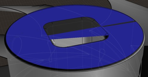
7. If you delete that square plug you can then show naked edges (http://moi3d.com/forum/index.php?webtag=MOI&msg=6051.2) to see where it was supposed to be. There is a very skinny ring there, only 0.0017 units wide.

A: This observation is what made me think that the import issues might be due to insufficient floating point accuracy. Maybe double precision is needed instead of single precision. I have no idea whether freeCAD, 123D Design or eDrawings use double precision or single precision floats but if changing all float variables in MOI's code to double precision is an easy change with no complex or problematic implications or ramifications, it might be worth it to see whether it fixes the issue.

There shouldn't be any square plug. I'm not sure which of the surfaces shown in this cross-section view in 123D Design are getting turned into that square plug :


8. That can generally cause problems having such a small width. But if you select the object you can then use Construct > Planar to fill it in and then it all seems to be ok after that.

A: I'm really really used to working only with solids, only in 123D Design, not with individual surfaces or edges / curves, except at the sketching stage, in 123D Design. That's why I hardly do any modelling in MOI, except for Twist or Flow ops on imported models. I think a better solution for me would be if there was a particular CAD format which is known to be the easiest for MOI3D to handle (either its native internal representation of CAD models or the closest format to that) and import and which could be expected to import most reliably. Then I could try converting to that format using freeCAD, from .dwg, .dxf, .sat or .step files which I can export from 123D Design, before importing the converted model into MOI.

Conversion to an intermediary format before actual import might also be a good workaround in the future. Maybe you could use Open Cascade or Coin 3D to import 3rd party CAD files to an intermediary format or to MOI's own native format or the closest format to its internal representation. And then actually import the file resulting from the conversion to the intermediary or native format of MOI rather than original, initial 3rd party CAD file itself. Just speculating, I might be completely off-base.

9. If I understand you correctly those seams are in spots where a surface has a hole in it. Most polygon mesh formats do not have the concept in them of a polygon with an internal hole in it, so when there is a hole in a surface after it has been subdivided, the polygon will be divided through the hole so as to bridge the outer and interior loop so it can be represented by a regular polygon instead of a polygon with an internal hole "island".

A: I'm ok with seams, I want the seams and I always export models with vertex welding de-activated because it avoids vertex normal averaging where it's best to not average vertex normals. The issue is that there are some redundant seams being created. I've highlighted what I mean in the following image. The blue lines are seams where vertices were duplicated upon export from MOI. The models are were exported 'triangles only'. No ngons are used. The blue seams are between triangles that make up the mesh surface. However, there's more seams being created than should be necessary. I highlighted the ones I think are redundant in red.


Thank you for all of the information, the work on 3.0 and 4.0 and for all the time you're taking to address people's inquiries and requests.

  Reply Reply More Options
Post Options
Reply as PM Reply as PM
Print Print
Mark as unread Mark as unread
Relationship Relationship
IP Logged

Previous
Next
 From:  Michael Gibson
9266.163 In reply to 9266.162 
Hi Larry,

re:
> Maybe a different geometry kernel might help, like Open CASCADE or Coin 3D?

Every different geometry kernel tends to have its own quirks and problems in different areas. So it's possible it could help but it's more like it's exchanging one set of problem areas for a different set of problem areas. It's also an extremely time consuming area of work.

Coin3D would not help at all since I don't think it implements any CAD solids file import, it's a toolkit for different things than that like managing a scene graph.


re:
> Can geometry kernel improvements to importing be made in 5.0?

Hopefully yes but I don't know much right now about what will be the focus areas for MoI v5 so I'm not able to make any promises right now about what will be done for v5.

There have been improvements to importing in every release of MoI though, so it would be pretty unusual if there weren't any for v5 as well. I have a general sense that the most problematic area for imports is in dealing with closed surfaces so it is possible that some attention to that particular area may yield a good improvement.


re:
> Is there a particular CAD model file which is easiest for MOI to handle?

That would be .3dm import, it's the closest to how MoI represents models internally and so involves the least amount of processing and manipulation of trimming boundaries.


re:
> a) by an index variable value range overrun?

Highly unlikely.


> Maybe an index variable is used in a loop somewhere in the import routine for .sat or .step files and the value it reaches
> exceeds the value range of the data type used? Maybe switching all index variables and counters in the code to 64 bit
> integer data types would fix obscure bugs and possibly also this one?

Well a 32-bit integer can hold a count up to 4294967295 and there is no list of entities in your propeller file that comes within very many orders of magnitude of that.


> b) by floating point variables with insufficient accuracy? Maybe there's snapping occurring when the software
> performs array indexing by checking a given float variable's or float array position's value to others before
> deciding whether to add it as a new array position or just as an index to an already existing position, which
> is actually supposed to be slightly different in value but with a difference too small for 32 bit floating precision?
> And so what should be two different positions in the array collapse to a single position?

The file import process uses 64-bit double precision floating point values throughout and so it can't be this problem either.

There can be different kinds of accuracy problems but they're about a "fitting tolerance" accuracy and not low level floating point arithmetic accuracy.


> I have no idea whether freeCAD, 123D Design or eDrawings use double precision or single precision floats but
> if changing all float variables in MOI's code to double precision is an easy change with no complex or problematic
> implications or ramifications, it might be worth it to see whether it fixes the issue.

MoI already uses double precision floating point for all geometry processing, single precision is only used in the display engine when sending display data to the video card.


> There shouldn't be any square plug. I'm not sure which of the surfaces shown in this cross-section view in 123D
> Design are getting turned into that square plug :

The square plug is coming from the "underlying surface", the plane surface that is underneath the trim curves. If you delete it then you can use the show naked edges scripts from the link above to see where the really skinny piece is at:


> I've highlighted what I mean in the following image. The blue lines are seams where vertices
> were duplicated upon export from MOI. The models are were exported 'triangles only'. No ngons are
> used. The blue seams are between triangles that make up the mesh surface. However, there's
> more seams being created than should be necessary. I highlighted the ones I think are redundant in red.

Are you seeing these seams only with MeshMixer or are you also seeing them in other programs as well?

It looks like it's probably an issue specific to MeshMixer where it is not liking to combine very skinny triangles. You could try adjusting your meshing settings on export to reduce the formation of long skinny triangles, the "Divide larger than" setting can help with that:


Hope that helps! - Michael

  Reply Reply More Options
Post Options
Reply as PM Reply as PM
Print Print
Mark as unread Mark as unread
Relationship Relationship
IP Logged

Previous
Next
 From:  LarryV
9266.164 In reply to 9266.163 
Hello Michael,

Thank you for your reply addressing all of my points and for taking so much time to answer everyone's questions and especially with my walls of text.

1. Hopefully yes but I don't know much right now about what will be the focus areas for MoI v5 so I'm not able to make any promises right now about what will be done for v5.

A: Thank you! Will upgrade to 4.0 as soon as the release version is out and then hold on tight for 5.0. Can we get staggered releases for 5.0 for Windows and MacOS, if 5.0 is ready for one OS earlier than the other? Also, if you perform improvements on importing in 5.0, can you please keep my step files on hand to test with as well?

2. There have been improvements to importing in every release of MoI though, so it would be pretty unusual if there weren't any for v5 as well. I have a general sense that the most problematic area for imports is in dealing with closed surfaces so it is possible that some attention to that particular area may yield a good improvement.

A: The models I import to MOI are solids only, so closed surfaces.

3. That would be .3dm import, it's the closest to how MoI represents models internally and so involves the least amount of processing and manipulation of trimming boundaries.

A: Thank you. I downloaded the trial version of CAD Exchanger and was able to convert the mould model to .3dm with that but it still did not import correctly in MOI 3.0. I've attached it. So I guess I'll need to hang on tight for 5.0 for exporting some of my CAD models to .obj.

4. The file import process uses 64-bit double precision floating point values throughout and so it can't be this problem either. MoI already uses double precision floating point for all geometry processing, single precision is only used in the display engine when sending display data to the video card.

A: Thank you, that's very impressive.

5. The square plug is coming from the "underlying surface", the plane surface that is underneath the trim curves. If you delete it then you can use the show naked edges scripts from the link above to see where the really skinny piece is at:

A: Thank you. I was able to more clearly see and find the surface by cutting the model in half after importing it in MOI. I highlighted a surface behind the actual problem surface so that it's easier to see in this screenshot :


Sometimes import issues occur with curved surfaces rather than flat ones, which is a challenge for me to correct in MOI, especially since I'm used to working only with solids.

5. Are you seeing these seams only with MeshMixer or are you also seeing them in other programs as well?

A: In the past, I used to also be able to highlight these with Meshlab 32 bit, on an older PC. But the latest version of Meshlab 64 bit no longer seems to offer that functionality. I've not yet found any other software that can highlight non-manifold edges to corroborate the issue. So I cannot check whether it's just Meshmixer showing thin triangles as actual cuts or seams in the mesh.

6. It looks like it's probably an issue specific to MeshMixer where it is not liking to combine very skinny triangles. You could try adjusting your meshing settings on export to reduce the formation of long skinny triangles, the "Divide larger than" setting can help with that:

A: I'm not using Mesh Mixer to combine vertices or perform any changes to the mesh at all. I only use Meshmixer to inspect the meshes of .obj files exported from MOI, to see where the mesh is separated into distinct triangle islands due to vertex duplication by highlighting seams which should be the edges of mesh islands. However, I could see how it may be possible for the way Meshmixer highlights seams to also highlight very very close edges of the same triangle even though those aren't actually cuts/seams in the mesh.

If that's the case then I consider the issue resolved or a non-issue to begin with. Unfortunately, I cannot check and confirm that it's Meshmixer misrepresenting the edges of very thin triangles as a seam or cut in the mesh.

If you can confirm that those redundant seams that got highlighted in MeshMixer (and which I highlighted with red in the screenshots) aren't actually cuts/seams in the mesh and are instead misrepresented as such by Mexhmixer then that would give me peace of mind as this is the only other issue I have with MOI currently, besides importing some models from CAD.

I only used the 'Divide Larger than' on curved surfaces because it made no sense to also use on flat surfaces as well as it would just inflate the poly count needlessly. Moreover, the flat surfaces that neighbour curved surfaces seem to get extra triangles as well, so that their vertices match up to those of their neighbouring curved surfaces even if their corresponding mesh islands aren't actually connected. So I hadn't thought about dividing flat surfaces as well.

My only concern is whether or not additional seams shown by MeshMixer are indeed extra cuts in the mesh. If that's not the case then exported meshes containing thin or small triangles is certainly not an issue.

Thank you for al the time you take to look into and answer questions and even help with models!

Best regards!

  Reply Reply More Options
Post Options
Reply as PM Reply as PM
Print Print
Mark as unread Mark as unread
Relationship Relationship
IP Logged

Previous
Next
 From:  Michael Gibson
9266.165 In reply to 9266.164 
Hi Larry,

re:
> Can we get staggered releases for 5.0 for Windows and MacOS, if 5.0 is ready for one OS earlier
> than the other?

They're built from a common code base in MoI v4 so they are ready at the same time. There usually isn't any separate porting process that needs to be done just for one OS. Not now anyway - it did take a lot of work to arrive at this state but it's infrastructure work that does not generally need to be repeated again.


> Also, if you perform improvements on importing in 5.0, can you please keep my step files on hand to test with as well?

Yup!


> The models I import to MOI are solids only, so closed surfaces.

So by "closed surface" I was meaning something like a cylinder surface that has a "seam edge" in it where the surface is closed in one direction. It's these kinds of surfaces that different CAD systems can have pretty different ways of representing trimming boundaries.


> I downloaded the trial version of CAD Exchanger and was able to convert the mould model to .3dm
> with that but it still did not import correctly in MOI 3.0. I've attached it.

Hmmm yes this seems to be quite a bit worse than the STEP import. There seems to be a lot of messed up UV trim curves being generated. I'll try to investigate it some to see if I can figure out why that is happening.


> If that's the case then I consider the issue resolved or a non-issue to begin with. Unfortunately, I cannot check and
> confirm that it's Meshmixer misrepresenting the edges of very thin triangles as a seam or cut in the mesh.

Can you please upload the .obj file for this one here? :


I can take a look at it to see whether there is any actual seam in there or if it's a really skinny triangle. It would be good for me to test with the same mesh settings that you used when generating it.


> I only used the 'Divide Larger than' on curved surfaces because it made no sense to also use on flat surfaces as
> well as it would just inflate the poly count needlessly.

It's just a way you can reduce very skinny triangles if those are undesirable for what you're doing. They're kind of hard to reduce without using a different triangulation method which would be a lot more time consuming.

Thanks,
- Michael
Attachments:

  Reply Reply More Options
Post Options
Reply as PM Reply as PM
Print Print
Mark as unread Mark as unread
Relationship Relationship
IP Logged

Previous
Next
 From:  Michael Gibson
9266.166 In reply to 9266.164 
Hi Larry, re: .3dm file from CAD Exchanger not working better - does CAD Exchanger have any option in it for what version of .3dm it will write out? If so can you try writing as a Rhino v2 .3dm file? That may avoid what seems to be the problematic area.

- Michael
  Reply Reply More Options
Post Options
Reply as PM Reply as PM
Print Print
Mark as unread Mark as unread
Relationship Relationship
IP Logged

Previous
Next
 From:  LarryV
9266.167 In reply to 9266.166 
Hey Michael,

Again, thank you for all the time you've taking to extensively answer all the inquiries in my walls of text.

1. Hi Larry, re: .3dm file from CAD Exchanger not working better - does CAD Exchanger have any option in it for what version of .3dm it will write out? If so can you try writing as a Rhino v2 .3dm file? That may avoid what seems to be the problematic area.

A: CAD Exchanger lets you choose which version of Rhino .3dm to export as. The first time I converted the .step file to .3dm with it I defaulted to exporting as a Rhino 6 .3dm but when I tried to open that in MOI nothing displayed at all. So I then exported again but as a Rhino 5 .3dm and that's the .3dm file I attached to my last reply.

I've now exported the .3dm as a Rhino 2 one :


and it appears to import better in MOI for the most part. But there still appear to be artefacts:


And the 5 different components in the original .step file are regarded by MOI as the same piece, when imported from the Rhino 2 .3dm file. So if I use this approach, I'll need to export each component to its own .step file and then its own .3dm file individually.

Moreover, when I exported an .obj file from the Rhino 2 .3dm of the model, with all the solids merged into one, there were tessellation issues with the obj model :


I thought maybe this is because all of the solids got wrongly merged together into one upon conversion from .step to Rhino 2 .3dm. So I then opened the original .step file in 123D Design again, deleted the 4 quarter mould pieces and kept just the cage and only exported that as a .step file. Then I converted that .step file to another Rhino 2 .3dm file and imported that into MOI. However, the tessellation issues were worse now :


These are the settings I used to export that .obj, from the Rhino 2 .3dm file of just the cage, without the 4 additional parts inside :


Unfortunately, it seems I deleted the original, native .123dx save of the model, from which I exported the original .step file containing all 5 components of the model. I only retained that one original .step file so I can't try to only export just the cage as its own .step file directly from the native .123dx save, to then convert that .step file of the one component to Rhino 2 .3dm and import that into MOI to see if it would make a difference. I don't think it's likely it would.

MOI does see both the Rhino 2 .3dm of all 5 pieces merged into one solid as a solid (not a Joined SRF) and the Rhino 2 .3dm of just the cage itself as a solid as well, not a joined SRF. So I don't think that the issues are due to the .step files I am converting from themselves being corrupted or faulty in some way. Also, I take care when modelling to never do things which might be ambiguous to the software 123D software I use and result in non-manifold edges or non-watertight solids.

I uploaded a 7z archive of :

a) The original .step file with all 5 components, converted to Rhino 2 .3dm instead of Rhino 5 .3dm (mould.quadlobe.toy.rhino.2.b.3dm).
b) .step file obtained by re-opening the original .step file with all 5 components in 123D Design, deleting the mould components and exporting just the cage (cage.only.stp).
c) .3dm file obtained by converting that new .step file to Rhino 2 .3dm (cage.only.3dm).

You can get the file at : https://drive.google.com/open?id=1N3Ebs5gmhwbd-oZst1bFXpTeiDRpT4Dq .

All conversions to .3dm were done with CAD Exchanger as that's the only other software I currently have that supports importing .step and exporting .3dm.

2. It's just a way you can reduce very skinny triangles if those are undesirable for what you're doing. They're kind of hard to reduce without using a different triangulation method which would be a lot more time consuming.

A: Thank you. However, the skinny triangles are non-issue for me, as long as they're not redundant cuts. My only concern is whether those additional seams shown by MeshMixer are false positives or they are indeed actual cuts / borders between islands in the mesh. If they aren't actual cuts or borders, it's a non issue and I'll stop using Meshmixer to check for this since it would mean it's generating false positives.

If they are actual cuts in the mesh, it would be nice if they can be prevented in 4.0 but it's not really an issue if they can't be helped. As long as the redundant cuts on the top/center/tip of curved surfaces don't result in the normals of vertices along those cuts being parallel to the face normals of the respective neighbouring triangles they belong to rather than divergent from those respective triangles' face normals.

For instance here :


there's additional cuts between each of the triangles which share that one vertex, right at the tip of the circular spherical cap. Even if those extra seams / cuts are indeed there, as long as the normals of the duplicated vertices are the same between the duplicated vertices rather than divergent from each other and parallel to their respective triangles' face normals, the extra cuts shouldn't matter when rendering.

This does indeed appear to be the case but can't say for sure due to the small size of the triangles in question it's hard to say for sure whether flat shading is going on or not. It doesn't seem to be resulting in flat shading, that I can tell.

Even if this results in flat shading, that's not an issue on flat faces :


3. Can you please upload the .obj file for this one here? :

A: Sure. I've uploaded a .7z of them here : https://drive.google.com/open?id=1xwWi19v1ORaR0eN-MtpjuVJ56ffxnh-z . You can also download the .obj files of just about any of my impeller models from grabCAD and they'll show the extra seams on the bottom plane and on the tips/tops/centers of bulging circular surfaces or sphere caps.

The ones here : https://grabcad.com/larry.v-1/models?page=4 . You can also download the .step model of any of them as well.

This one here : https://grabcad.com/library/impeller-design-02-2-1 doesn't appear to be a false positive due to skinny triangles. I've uploaded both its .step and .obj here :

https://drive.google.com/open?id=1VRlXPAT2w7gAgpBk9cftSscmdqZ5r-8I

It's not a bid deal if this can't be helped. I'm only asking about it because it's triggering my OCD :)

4. I can take a look at it to see whether there is any actual seam in there or if it's a really skinny triangle. It would be good for me to test with the same mesh settings that you used when generating it.

A: I checked with a different model and it doesn't appear to be due to skinny triangles. That's the model here :

https://drive.google.com/open?id=1VRlXPAT2w7gAgpBk9cftSscmdqZ5r-8I

Generally, I use the settings shown above or values close to them. Depending on the complexity of the model and the triangle count of the resulting mesh. For instance, for 'Divide larger than' I normally choose .1 and for avoid smaller than I choose '.01~.02' but that would result in way too high a poly count for the model of the cage.

Sorry to be taking so much of your time with this minutiae.

Best regards,

Larry.

EDITED: 25 Jul 2019 by LARRYV


  Reply Reply More Options
Post Options
Reply as PM Reply as PM
Print Print
Mark as unread Mark as unread
Relationship Relationship
IP Logged

Previous
Next
 From:  Michael Gibson
9266.168 In reply to 9266.167 
Hi Larry, so for the MeshMixer unexpected seam display, I closely examined your file impeller05.obj which was this one:


There is indeed a seam here:


There is no seam or "island separation" to be found in the other area you circled though. I tested this by isolating the bottom face in Rhino and pulling the points, each one is a single point connected to everything else and they don't pull apart. Here they are each one point that has a long edge coming from it pulled slightly to the outside of the original circle:


So there is no seam to be found at that spot, there is however some very skinny triangles and a particularly skinny one in that area. It is just quite skinny though, not reversed.

So my best guess is that MeshMixer does not like such skinny triangles, maybe it considers it within some tolerance of being non-manifold.


re:
> This one here : https://grabcad.com/library/impeller-design-02-2-1 doesn't appear to be a false
> positive due to skinny triangles. I've uploaded both its .step and .obj here :
>
> https://drive.google.com/open?id=1VRlXPAT2w7gAgpBk9cftSscmdqZ5r-8I

I took a close look at the flat face of impeller02.2.obj using the above process and could not find any seams other than the one horizontal one.


re: saving as v2 - that's too bad that wasn't without it's own issues. I tested loading in your cage.only.3dm file into Rhino and also saw various meshing artifacts in there as well, here's what it looks like in Rhino:


So the save as v2 won't be viable, it has a different kind of messed up UV curves. So the problem in the original .3dm file is that MoI isn't able to use the UV trim curves on cylinders, cones, and spheres special case type objects. That means it has to make its own UV curves but there's a bug in that process somewhere. When you do a "save as v2", those special objects are converted into regular NURBS surfaces which means that MoI is able to use the UV curves from the v2 file. But the conversion of the UV curves from analytic UV space to NURBS UV space is not very good in the OpenNURBS toolkit. The weird artifacts in both MoI and Rhino are because of poor quality UV curves.

I'll investigate some more to try and see if I can figure out why MoI's UV trim curve generator isn't doing too well on your original converted 3dm file. It looks like it's sometimes going in the wrong direction when the first or last points of the 3D edge curve are on the seam edge of a closed surface.

Thanks,
- Michael

  Reply Reply More Options
Post Options
Reply as PM Reply as PM
Print Print
Mark as unread Mark as unread
Relationship Relationship
IP Logged

Previous
Next
 From:  Michael Gibson
9266.169 In reply to 9266.167 
Hi Larry, so I was able to find a bug in MoI's 3DM importer that was messing up the mould.quadlobe.toy.3dm import, that's the first one that you posted from CAD Exchanger in Rhino v5 format.

I've fixed that up so the next v4 beta will be able to import that file ok, thanks for reporting it.

- Michael
  Reply Reply More Options
Post Options
Reply as PM Reply as PM
Print Print
Mark as unread Mark as unread
Relationship Relationship
IP Logged

Previous
Next
 From:  LarryV
9266.170 In reply to 9266.169 
Hello Michael,

Thanks for the update! That's fantastic.

I've converted the problematic propeller model to Rhino 5 .3dm as well and testing I found it's likewise not importing correctly in 3.0.

Can you please test your latest v4 beta version with this one as well? I've attached it to this reply.

Thank you for your time and consideration.

Best regards,

Larry.
Attachments:

  Reply Reply More Options
Post Options
Reply as PM Reply as PM
Print Print
Mark as unread Mark as unread
Relationship Relationship
IP Logged

Previous
Next
 From:  Frenchy Pilou (PILOU)
9266.171 
Works as solid for obj export in V4 ;)

---
Pilou
Is beautiful that please without concept!
My Moi French Site My Gallery My MagicaVoxel Gallery
  Reply Reply More Options
Post Options
Reply as PM Reply as PM
Print Print
Mark as unread Mark as unread
Relationship Relationship
IP Logged

Previous
Next
 From:  Michael Gibson
9266.172 In reply to 9266.170 
Hi Larry, yup good news the same bug fix solves that one as well. Here's what it will look like in the next v4 beta with the bug fix:


Thanks for reporting it! I'm still going to investigate the step import some more but it is usually quite a bit easier for me to figure out what's going on with .3dm imports.

- Michael
Attachments:

  Reply Reply More Options
Post Options
Reply as PM Reply as PM
Print Print
Mark as unread Mark as unread
Relationship Relationship
IP Logged

Previous
Next
 From:  Michael Gibson
9266.173 In reply to 9266.171 
Hi Pilou,

re:
> Works as solid for obj export in V4 ;)

Nope, it's not working in the current v4 beta, it just looks ok from that angle because the messed up part is on the bottom.

But it will work fine in the next v4 beta though.

- Michael
  Reply Reply More Options
Post Options
Reply as PM Reply as PM
Print Print
Mark as unread Mark as unread
Relationship Relationship
IP Logged

Previous
Next
 From:  Frenchy Pilou (PILOU)
9266.174 In reply to 9266.173 
This ?

---
Pilou
Is beautiful that please without concept!
My Moi French Site My Gallery My MagicaVoxel Gallery
  Reply Reply More Options
Post Options
Reply as PM Reply as PM
Print Print
Mark as unread Mark as unread
Relationship Relationship
IP Logged

Previous
Next
 From:  LarryV
9266.175 In reply to 9266.172 
Hello Michael,

Thanks a lot for confirming! Can't wait for the release v4 release!

About that, will the release 4.0 version need to be installed over 3.0, in the same folder? As an add-on or expansion of sorts? Or will it be a separate installation?

If it comes as a separate installer which can be installed in a separate folder, if I install it over V3 would it retain the plugins I installed? I'm sorry if these questions were already asked and answered earlier in this thread.

Thanks for your time and consideration.

Best regards!

Larry.
  Reply Reply More Options
Post Options
Reply as PM Reply as PM
Print Print
Mark as unread Mark as unread
Relationship Relationship
IP Logged

Previous
Next
 From:  LarryV
9266.176 In reply to 9266.174 
Hey Pilou,

That's indeed where the import issue in 3.0 is and it looks similar to your screenshot from the current beta of 4.0 so it was probably the same issue as in 3.0.

Best regards,

Larry.
  Reply Reply More Options
Post Options
Reply as PM Reply as PM
Print Print
Mark as unread Mark as unread
Relationship Relationship
IP Logged

Previous
Next
 From:  Michael Gibson
9266.177 In reply to 9266.174 
Hi Pilou, yes that's the problem area, it will be ok in the next v4 beta though.

- Michael
  Reply Reply More Options
Post Options
Reply as PM Reply as PM
Print Print
Mark as unread Mark as unread
Relationship Relationship
IP Logged

Previous
Next
 From:  Michael Gibson
9266.178 In reply to 9266.175 
Hi Larry also I should mention that I'm hoping that the next v4 beta will be the last one and after that I'll switch to a very conservative mode trying not to make any more changes if possible to avoid introducing new bugs for the final v4 release. So if you have any other .3dm files that don't come across well now would be the time to send them to have a chance at getting them fixed for v4.

So far it seems that CAD exchanger .3dm transfer is working well other than this one particular bug though.


> About that, will the release 4.0 version need to be installed over 3.0, in the same folder? As an add-on
> or expansion of sorts? Or will it be a separate installation?

It's meant to be a separate installation, it's best not to try and install it directly in the same folder as v3.


> If it comes as a separate installer which can be installed in a separate folder, if I install it over V3
> would it retain the plugins I installed?

I'm not quite sure what would happen. It's best not to try and intermingle a v3 and a v4 installation directly over top of each other in a single install folder. It's intended that v3 and v4 should be in separate folders. Probably what would happen is you would have a v4 that worked and the current v3 installation would be broken. Many of the binaries for v3 and v4 have the same file name like MoI.exe, etc... so if you tried to put them in the same folder the v3 ones would get overwritten.

For plugins, most plugins are installed by copying them into the commands folder, you would just copy those from v3's commands folder into v4's commands folder. Also v4 now supports an additional commands folder located in appdata, outside of the main installation folder. It's good to put plugins there instead because then future versions will find them them there instead of needing to copy them around.

- Michael
  Reply Reply More Options
Post Options
Reply as PM Reply as PM
Print Print
Mark as unread Mark as unread
Relationship Relationship
IP Logged

Previous
Next
 From:  LarryV
9266.179 In reply to 9266.178 
Hey Michael!

It doesn't look like I have any more models which don't import correctly either as .step files or as .3dm files, after conversion with CAD Exchanger. From what I can tell, it looks like I'll be able to reliably use this pipeline going forward.

Thank you!

Best regards,

Larry.
  Reply Reply More Options
Post Options
Reply as PM Reply as PM
Print Print
Mark as unread Mark as unread
Relationship Relationship
IP Logged

Previous
Next
 From:  Michael Gibson
9266.180 In reply to 9266.179 
Thanks Larry, that's great!

- Michael
  Reply Reply More Options
Post Options
Reply as PM Reply as PM
Print Print
Mark as unread Mark as unread
Relationship Relationship
IP Logged
 

Reply to All Reply to All


Show messages:  1-20  …  101-120  121-140  141-160  161-180  181-200  201-218