Top 5 Features list for V3 !
 1-5  …  366-385  386-405  406-425  426-442

Previous
Next
 From:  Mike K4ICY (MAJIKMIKE)
3628.406 In reply to 3628.405 
Thanks Michael, good luck!
  Reply Reply More Options
Post Options
Reply as PM Reply as PM
Print Print
Mark as unread Mark as unread
Relationship Relationship
IP Logged

Previous
Next
 From:  Grendel
3628.407 
I'm still holding out for a circular selection function...
  Reply Reply More Options
Post Options
Reply as PM Reply as PM
Print Print
Mark as unread Mark as unread
Relationship Relationship
IP Logged

Previous
Next
 From:  Mike K4ICY (MAJIKMIKE)
3628.408 
Hi Michael,

I think you mentioned that it may be possible to add or remove isocurve control elements (or row of grid points) within a surface, basically allowing for more or less definition in that surface.

With that idea, I realized that it might be possible to move the position of the "seam" on a closed surface without disturbing the surface... or maybe I saw this somewhere.

It's not possible now, but would be useful for times when you needed to use Blend to close the open end of a closed surface, among other things.


Could this be a feature nestled within some other feature?


So, a way to re-adjust the position of the seam on a closed surface... possible?

Uh oh... I think I just asked for the '3D' version to moving the (start/end) seam point in a closed curve.

(back-burner, just an idea)

Thanks
  Reply Reply More Options
Post Options
Reply as PM Reply as PM
Print Print
Mark as unread Mark as unread
Relationship Relationship
IP Logged

Previous
Next
 From:  Michael Gibson
3628.409 In reply to 3628.408 
Hi Mike, I do want to add a "relocate closed surface seam" mechanism, but it will probably have to be a specialized tool to do it, I don't really see how it would be bundled in to some other already existing function... Or do you have a particular feature that you were thinking of that would include this as some kind of extension to it?

- Michael
  Reply Reply More Options
Post Options
Reply as PM Reply as PM
Print Print
Mark as unread Mark as unread
Relationship Relationship
IP Logged

Previous
Next
 From:  Mike K4ICY (MAJIKMIKE)
3628.410 In reply to 3628.409 
Michael,

I do see where it could use a specific tool command. Especially if you could apply it to closed curves as well as closed surfaces.

Not sure which menu beside 'Edit'.

Maybe it would start life as a text command like "Rebuild"?

Thanks,
Mike
  Reply Reply More Options
Post Options
Reply as PM Reply as PM
Print Print
Mark as unread Mark as unread
Relationship Relationship
IP Logged

Previous
Next
 From:  Ditto
3628.411 
For background, I am coming from Rhino, I am actually going alternating between them. And I am very used to use the keyboard to type commands instead of clicking them. In that sense, MoI is a bit more a hindrance to me.

To add to this wishlist:

1/ The "Offset Curve" command could accept negative numbers for inward and positive numbers for outward direction.

2/ Long shortcuts: Some commands, either builtin or addon scripts, have the same name as Rhino commands, and I happily hit Tab to use them. It would be fabulous to be able to assign long shortcuts to commands. For script files (in the command directory), this is obviously a no-brainer, but the key to "script:..." lines in the options could be longer.

A format like: "Key | Long | Command" would be ideal. The Key works as usual (and can be empty), and Long would be searched in addition to the commands directory if Tab is hit.

3/ Just to ask for too much : A list drop down as in Rhino for the possible commands would win extra karma point for Michael.

Thanks for considering these ideas!

Ditto


** And I hope this thread, and my posting, still gets some attention and much support ;)
  Reply Reply More Options
Post Options
Reply as PM Reply as PM
Print Print
Mark as unread Mark as unread
Relationship Relationship
IP Logged

Previous
Next
 From:  Michael Gibson
3628.412 In reply to 3628.411 
Hi Ditto,

re #1 -
> The "Offset Curve" command could accept negative numbers for inward and positive numbers for outward direction.

The problem with that is that open curves (like say a line for example) do not particularly have any specific "inward" or "outward" directions to them.

So that's why it asks you to pick a point on which side you want to offset to, that makes the command work with all kinds of curves and not only on closed curves alone.


re: #2 -
> 2/ Long shortcuts:

I think you're asking for the equivalent of a "command alias" in Rhino, is that correct? That's like a short name that you type in but that can internally expand to a longer name.

I wouldn't really see putting a type-in alias right in the shortcut keys UI since just in general MoI is not so focused on typing in command names, but I can probably set up a section of the moi.ini file where you could enter in some aliases.

- Michael
  Reply Reply More Options
Post Options
Reply as PM Reply as PM
Print Print
Mark as unread Mark as unread
Relationship Relationship
IP Logged

Previous
Next
 From:  Mike K4ICY (MAJIKMIKE)
3628.413 
Hi Michael,

Sorry, my mind was spinning tonight after discovering some new Lighting Options... ;-)

- I know you may have plans for enhancements to the lighting mechanism as well as for UI control in the distant future...
aside from the possibility of environment mapping, are there any other possibilities, like additional lights, specular additions, ambient occlusion or anything else that the standard DirectX engine may provide. Of course, all things optional to allow MoI to work well with older cards as well as exploiting the limitless powers of new ones.

- I notice that MoI's Viewport rendering is done with polys, as you can see the triangles within certain surfaces.
When I go to export to a non-NURBS format and choose a non-lines view while using the option for 4-sided N-gon output, the viewport image looks really nice!
So it's there and it works... Would you ever include a standard viewport option for rendering quads or poly+quads in normal use?

- The New and Improved-Improved-Blend... with the ability to add control shapes along the surface-route and those "rolled pencil" (?) perpendicular control shapes you were talking about. Hmmm. (just keep it on your list)

- Shearing... it's not just for sheep anymore. I've put a little thought into the viable need for this transformation, still - I keep finding myself wanting to go for the "shear" tool (or handlebar), with objects, yes, can be done with Flow, but I find myself wanting to do it with selected control points... It think it's a thing AI, PS, & Corel users are spoiled with.


Okay, all backburner, I'm actually anticipating being able to cut and paste (or export pdf and import) the MoI viewport as you've been working on. Now that is going to be cool!

Thanks.
  Reply Reply More Options
Post Options
Reply as PM Reply as PM
Print Print
Mark as unread Mark as unread
Relationship Relationship
IP Logged

Previous
Next
 From:  Michael Gibson
3628.414 In reply to 3628.413 
Hi Mike,

> aside from the possibility of environment mapping, are there any other possibilities, like additional lights,
> specular additions, ambient occlusion or anything else that the standard DirectX engine may provide.

Could you maybe clarify by what the "additional lights" part is about? MoI does currently generate a environment lighting map using 12 light sources to generate the map, it could be possible to have some other methods for generating the light map in the future, but it takes quite a bit of effort to do nice quality lighting and also figure out good controls for adjusting it.

Other stuff like ambient occlusion are difficult to do without using shaders and requiring kind of higher end cards.


> So it's there and it works... Would you ever include a standard viewport option for
> rendering quads or poly+quads in normal use?

Yeah it could be possible in the future to do some work for bringing in polygon models. But having rendering of them in place is I'm afraid only one small piece of the puzzle, selection interaction, UI and workflow planning and things like that are much more problematic than just display itself. One general problem with having mesh geometry at model time is having 2 very different kinds of models which don't interact with one another really well. It leads to problems like someone opens a polygon model file and then draws a sphere in MoI and then wonders why those 2 objects won't boolean with each other.


> The New and Improved-Improved-Blend... with the ability to add control shapes along the
> surface-route and those "rolled pencil" (?) perpendicular control shapes you were talking about.
> Hmmm. (just keep it on your list)

Yup, it's still on the list!


Re: Shearing
I'm still kind of hoping that a flexible enough cage edit command would be able to do this job rather than having a totally separate shear command.

- Michael
  Reply Reply More Options
Post Options
Reply as PM Reply as PM
Print Print
Mark as unread Mark as unread
Relationship Relationship
IP Logged

Previous
Next
 From:  Marc (TELLIER)
3628.415 In reply to 3628.414 
Yeah, cage edit would be awesome!

Marc
  Reply Reply More Options
Post Options
Reply as PM Reply as PM
Print Print
Mark as unread Mark as unread
Relationship Relationship
IP Logged

Previous
Next
 From:  Mike K4ICY (MAJIKMIKE)
3628.416 In reply to 3628.414 
> MoI does currently generate a environment lighting map using 12 light sources

Holy cow... And I would lovingly tweak every one of them! ;-)

So even I can admit to not understanding the process behind it all. Since MoI is intended to be easy-to-use and user-friendly straight out of the box, fancy lighting and rendering should, of course, not be a worry for anyone. Since Dinos' script and my tweaking, it's been nice to see more user screen-shots with certain familiar 'glossy' configurations.
Despite the use of more 'chromey' UI's in Rhino - which use the more power-card dependent OpenGL, MoI still takes the cake as far as overall visual appeal! I mean, the anti-aliased lines are worth every penny.

I'll leave it to you though. My main desire, of course, is for a bias for improvement in modeling tools over UI.


> 2 very different kinds of models which don't interact with one another really well. It leads to problems...

I remember you talking about that 'selection map' thing. Oh... It wasn't the inclusion of poly data (mixing of NURBS and Polys) I was thinking about, but the actual use of quads in MoI's vid-card view rendering of the NURBS objects...

Here's what I was getting at:


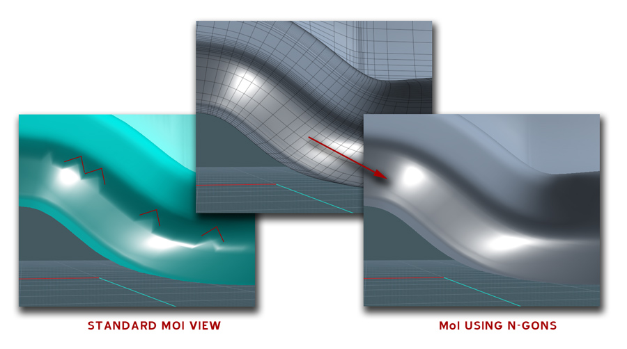
The screen capture on the left is from the actual editing viewport. You can see where the triangles are more evident... Phong shading can only do so much here.
The middle pic is what you see when you go to the export dialog to choose the tessellation details of the object. (same viewport, just different arrangement of polys sent to the vid card) But here, the option for wires+shades are active.
The capture to the right is with the shades showing alone. The triangles are gone because MoI is using squares. Since squares can better define the contour flow of a surface as far as lighting is concerned, it looks really smooth.

But if this also makes selection maps trickier to deal with, I can understand. I think this was what you were talking about.
So using triangles is easier on the selection interaction mechanism? Interesting.


> Yup, it's still on the list!
Kewel! :-)

>Re: Shearing: I'm still kind of hoping that a flexible enough cage edit command would be able to do this job rather than having a totally separate shear command.

I wish you the best of luck on the Cage Edit thing.
Would it work on a random selection of control points and not just objects?


Thanks Michael!
  Reply Reply More Options
Post Options
Reply as PM Reply as PM
Print Print
Mark as unread Mark as unread
Relationship Relationship
IP Logged

Previous
Next
 From:  wastzzz
3628.417 
One small request for me (quite simple I think) would be the implementation of a section tool. In any ortho view, you draw a section line. Then you choose a maximum distance for the elements that you want to be projected in the section (the new hidden line and silhouette mechanism will be necessary). For the elements intersecting the section, a simple intersect command will do it.
This request is all I ask.
M
  Reply Reply More Options
Post Options
Reply as PM Reply as PM
Print Print
Mark as unread Mark as unread
Relationship Relationship
IP Logged

Previous
Next
 From:  Michael Gibson
3628.418 In reply to 3628.416 
Hi Mike,

> The capture to the right is with the shades showing alone. The triangles are gone because MoI is using
> squares. Since squares can better define the contour flow of a surface as far as lighting is concerned,
> it looks really smooth.

It's actually still using triangles for the display in the second case too... The video card inherently only understands triangles, a square is sent over to the video card as 2 triangles.

The difference you're seeing there is not because of squares versus triangles but just that the one on the left has fewer triangles than the one on the right.

The one on the left is done for realtime display purposes, while the one on the right is done for a mesh export to a rendering program. It's important for the realtime display to be fast, so there are various shortcuts taken in order to speed things up which can have an adverse effect on quality. If this was not the case and it instead put an emphasis on quality instead of speed the bad side effect from that choice would be that you'd have to spend extra time waiting around for the display to update every time you did any change to a model.

It's just not practical for the real time display to try and have the qualities of a non-realtime final quality render.

Do you have "Add detail to inflections" turn on under Options > View > Meshing parameters? It can help to put in some additional triangle density in areas like that, that's basically what it's for. But it only tries to add in a couple of more subdivisions than what it would otherwise have.


> But if this also makes selection maps trickier to deal with, I can understand.
> I think this was what you were talking about.

No, I had misunderstood your question, I thought you were talking about quads and triangles because you wanted to have mesh object editing.


> I wish you the best of luck on the Cage Edit thing.
> Would it work on a random selection of control points and not just objects?

I'd think that it would be possible to do it that way.


- Michael
  Reply Reply More Options
Post Options
Reply as PM Reply as PM
Print Print
Mark as unread Mark as unread
Relationship Relationship
IP Logged

Previous
Next
 From:  Michael Gibson
3628.419 In reply to 3628.417 
Hi Max,

> One small request for me (quite simple I think)

If only it was actually simple for things like this!

One of the most difficult things with new features is to figure out where to put the feature in the UI so that it does not cause "feature bloat". When too many features pile up all over the UI it tends to make the UI become more complex. It's a big focus for MoI to avoid this kind of complexity and that means that it is a big issue to figure out where to put new features. If it's possible to incorporate the new feature as an option or natural extension of an existing command, then that can help a lot.

So some of the big questions for a "simple" feature like you're describing there (which is likely very much not as simple as you might think, you already mention needing to incorporate hidden line and silhouette display in it...) would be even just where to put the button in the UI to start with.

There are all kinds of complexities involved with this.... How is it exactly that the hidden line mechanism would come into play? I'm probably not really understanding the full scope of what you're asking to have here.

- Michael
  Reply Reply More Options
Post Options
Reply as PM Reply as PM
Print Print
Mark as unread Mark as unread
Relationship Relationship
IP Logged

Previous
Next
 From:  wastzzz
3628.420 In reply to 3628.419 
> One of the most difficult things with new features is to figure out where to put the feature in the UI so that it does not cause "feature bloat".
In the View Panel.

> I'm probably not really understanding the full scope of what you're asking to have here.

It's a section tool. Now I have to use Rhino to make sections out of my models, using plugins like the free "Section Tools" or the not-free "VisualARQ". But I don't own Rhino, I am using the trial version, and I'm using it just for that. Here:

1) I draw the section line.


2) I generate the section and export it in .DXF for linework editing and presentation.


But this is not just an architectural need. I am working for designers as well, and they always ask for sections. Plan, section, elevation: it's the design process.

EDITED: 4 Oct 2013 by WASTZZZ

Attachments:

  Reply Reply More Options
Post Options
Reply as PM Reply as PM
Print Print
Mark as unread Mark as unread
Relationship Relationship
IP Logged

Previous
Next
 From:  mjs (MSHIDELER)
3628.421 In reply to 3628.420 
I do not ask this question to be mean or a j-hole but to be serious so please don't read into it anything beyond my curiosity.

Many times throughout the forums people ask for some pretty complex features to try to make MoI more fit what they need. This is a $300, but awesome, design tool but I get the impression that with many of the people asking for extra features, or a better way to do some surfacing such as the automotive model that someone wanted to make but the tutorial book that I used was pretty much ignored because the output surfacing would not always be automotive quality. Well, the tutorial is to learn the techniques and not design a car. An automotive engineer does not design in a $300 tool.

Similarly with the thread regarding line weights for outside edges for drawings. Sure it would be nice but there are multiple low cost, free, or professional tools that can take care of this very issue.

Now, when you are asking for the section feature, which is a nice idea, but then you say that you are working with other designers that are always asking for something that is difficult to do in MoI, why not just buy Rhino. Do you initial work in MoI and then send it to Rhino for completion?

MoI is such a great tool for most work, up to a point like what you are running into, and at a price point where a hobbyist can justify using it. MoI also plays so well with other tools that you can do quite a bit of work in MoI and then port out to your finishing package. If MoI gets too complex it will lose its focused power and the price will eventually have to move up in order to have the amount of presence that it would take to support MoI.

I just fear scope creep with all the wants (most of which would rock but there are reasons why things sometimes require separate software packages) and the MoI starts to slide away from what makes it the shiz-nic. Simple, clean, plays well with other tools.

Best thing for MoI is to keep working the 2D and 3D design and feature sets (3D solids, surfacing, etc) which it already excels at and make sure to keep those areas at the top of the scale. A Rolls Royce that does a few focused things very well at a price point that allows anyone access to the tool is much more valuable than too many "I wish it could..." creeping in. I say this from the perspective that it sounds like many people requesting features are already working as designers which implies access to more funds and other tools from what a hobbyist would have.

Sure, I think it would be nice if I could do other things in MoI but I just finish in Rhino or spit files out for (God help me) GeoMagic (puking in the corner).

Back to wastzzz - if you are doing designs like this and being paid for it pony up and get Rhino. There are many other free / paid for addons that rock with Rhino but this does not mean that MoI gets displaced at all. MoI is an awesome tool for 70 to 95% of most design projects, in my tiny opinion.
  Reply Reply More Options
Post Options
Reply as PM Reply as PM
Print Print
Mark as unread Mark as unread
Relationship Relationship
IP Logged

Previous
Next
 From:  Michael Gibson
3628.422 In reply to 3628.420 
Hi Max,

> In the View Panel.

I'm kind of unsure about putting what's really a geometry generation tool inside of the View panel.


> It's a section tool. Now I have to use Rhino to make sections out of my models, using
> plugins like the free "Section Tools" or the not-free "VisualARQ".

Please keep in mind that both of those tools have been extensively worked on by developers whose main jobs are just doing those tasks.


> But this is not just an architectural need. I am working for designers as well, and
> they always ask for sections. Plan, section, elevation: it's the design process

There are a couple of different ways you can generate a section line already, you can draw in a line like you've shown there and then use Construct > Curve > Project to project the line onto the object, the result will be a section line:


Another way is to make a plane for where you want the section and then use Construct > Curve > Isect to generate intersection curves between the plane and your object.

- Michael

  Reply Reply More Options
Post Options
Reply as PM Reply as PM
Print Print
Mark as unread Mark as unread
Relationship Relationship
IP Logged

Previous
Next
 From:  wastzzz
3628.423 In reply to 3628.422 
Thank you Michael, I already experimented with the Isect command and it works fine for sectioned elements, but what I need is to project the elements that are far away from the line\cutting plane
  Reply Reply More Options
Post Options
Reply as PM Reply as PM
Print Print
Mark as unread Mark as unread
Relationship Relationship
IP Logged

Previous
Next
 From:  Michael Gibson
3628.424 In reply to 3628.423 
Hi Max,

> Thank you Michael, I already experimented with the Isect command and it works fine for sectioned
> elements, but what I need is to project the elements that are far away from the line\cutting plane

I guess I need a more detailed explanation from you - I'm just not familiar with the type of sectioning that you need. What kind of additional projection do you need, can you post an example with some simple objects?

- Michael
  Reply Reply More Options
Post Options
Reply as PM Reply as PM
Print Print
Mark as unread Mark as unread
Relationship Relationship
IP Logged

Previous
Next
 From:  Marc (TELLIER)
3628.425 In reply to 3628.424 
I think what Max means would be like cutting a model and then perform hidden line removal on the resulting geometry.


The result would deliver something like that:


Marc
Attachments:

  Reply Reply More Options
Post Options
Reply as PM Reply as PM
Print Print
Mark as unread Mark as unread
Relationship Relationship
IP Logged
 

Reply to All Reply to All


Show messages:  1-5  …  346-365  366-385  386-405  406-425  426-442