Show messages: All
1-2
3-14
From: bemfarmer
Incorporate Blends?
From: ed (EDDYF)
Hi Psygorn -
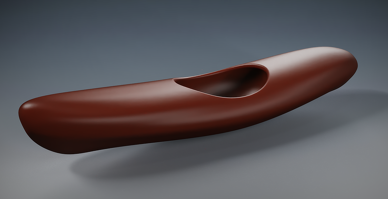
Here's my take on the kayak. I think the approach depends on if you need precision because you'll use the model to build one, or if you're making a model just for rendering a concept. There are a lot of posts on the Moi forum about modeling boats in general, and getting a precise result is not trivial.
My approach falls into the "make a model for rendering" category.
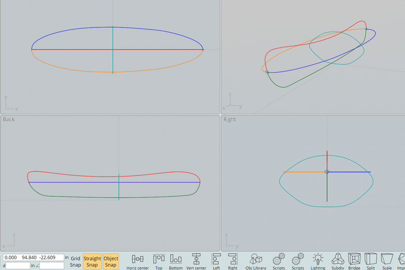
I think it will be difficult to piece together four networks and have the edges blend together as you want. My approach is to use one large network.
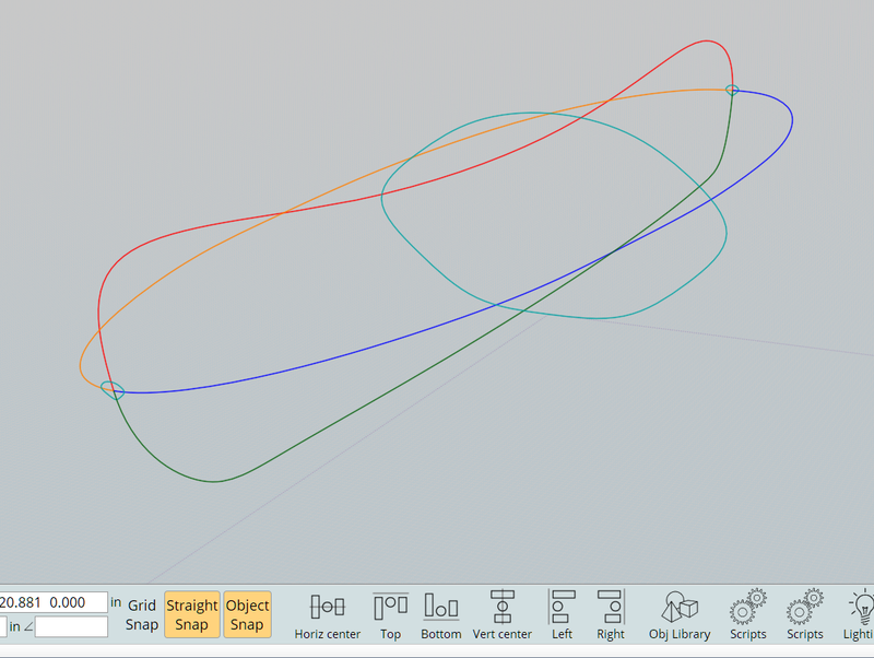
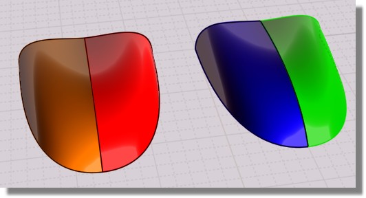
The Red & Green curves represent the side view and the ends must touch. The Orange & blue curves are mirrors that represent the top view, and the ends must meet at a single point with the Red & Green curves.
The two small cyan closed profile curves at each end are derivatives of the center profile curve. That is, they are resized and re-shaped via their control points so each of the three profiles has the same number of points. I don't know if a common point-count is necessary, but I like to make all profiles from copies of the central profile. The small end profiles accomplish two things: Their pointed shape at the bottom define the bow and stern, and they minimize pinching where the network is collapsing to the single point at each end.
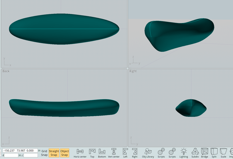
I used Network > Lighter to create the kayak. The nice thing about Networks is you can point edit, or move / resize, any of the curves afterwards and immediately see the effect on the network.
Ed Ferguson
From: Michael Gibson
Hi DrillBit, can you please post your .3dm model file?
Usually the best way in MoI to avoid sharp edges is to make one single larger Network instead of doing it in smaller sections. If you do it in sections you will end up with sharp corners between each section.
- Michael
From: Psygorn (DRILLBIT)
Hello Phiro,
thank you for your reply and I am sorry for my late reply!
No, I cannot post my file! I am using a trial version of Moi3D with no saving! The reason I am doing this is that I want to get familiar with it, currently I am a user of SolidWorks (it is the main modeling software in our office) However, I had the chance to meet with Moi3D and I really liked its speed or its philosophy which is built around speed! :-)
I just want to become sure of its capabilities so maybe I will switch to as main concept modeling tool in the close future.
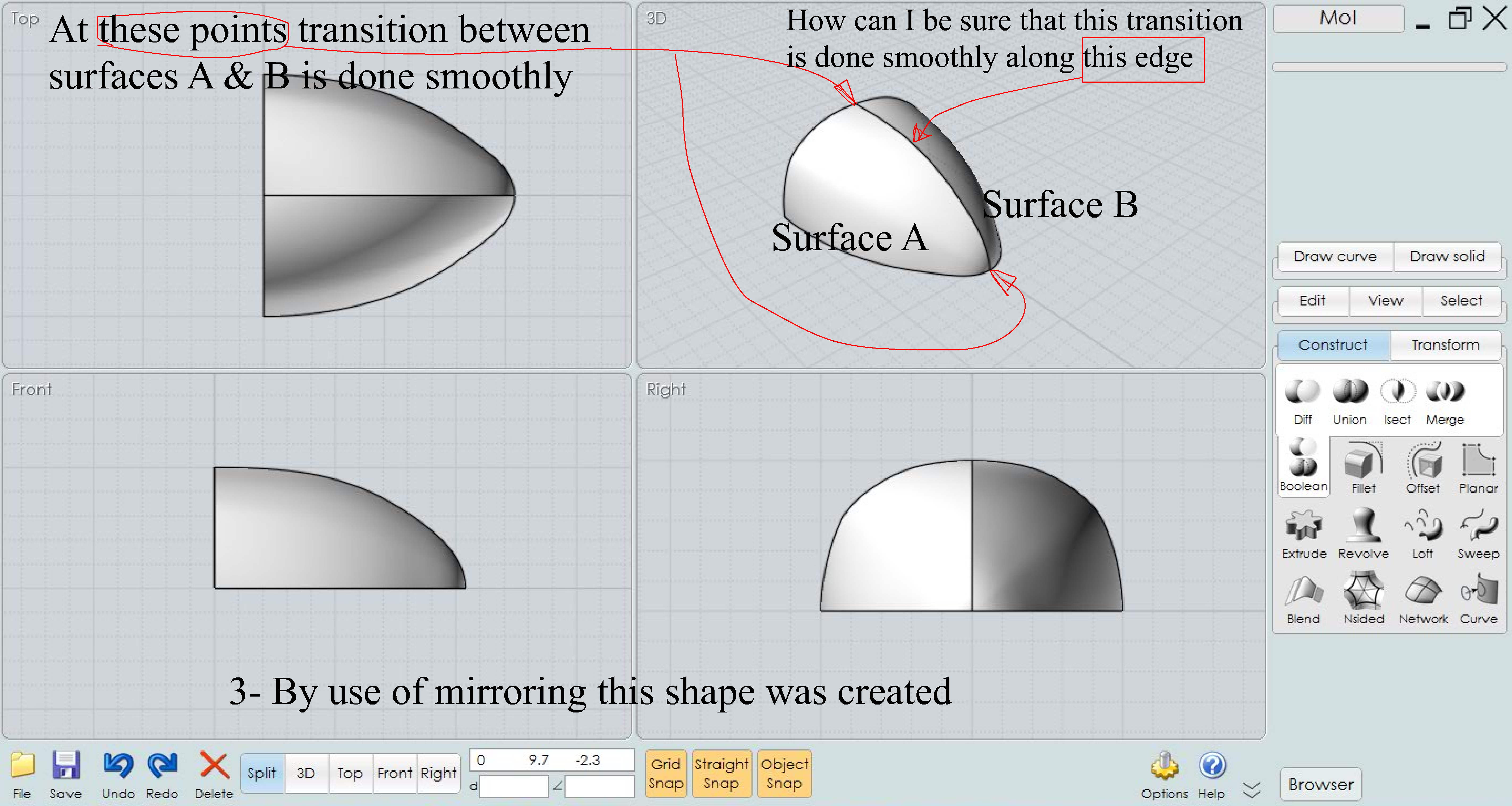
I have created these images to help you to see my process. :-)


Attachments:
 Moi_3D_Questions-1.png
Moi_3D_Questions-2.png
Moi_3D_Questions-3.png
From: Psygorn (DRILLBIT)
Hello and thanks for your reply Ed(EDDYF) and sorry for my late reply,
by "kayak" I meant sharp edges if you find the attached images in my reply for Phiro you can see my question in pictures. :-)
And thanks for your informative reply :-)
From: Psygorn (DRILLBIT)
Hello Michael,
Thanks for your reply and sorry for my late reply.
If you find the attachments in my reply for Phiro you can see my question in images. But I think u answered it already! so, I will ask you a new question How to create one large Network? just by mirroring my curves? Is that it? Well I will try it as soon as possible. :-)
From: Psygorn (DRILLBIT)
Hello Bemfarmer,
Thanks for your reply and sorry for my late reply! :-) I was kind of busy.
If you find the attachments in my reply for Phiro you can see my question in pictures!
From: Frenchy Pilou (PILOU)
Question 1 : You right : for be tangent you must have Control Points Aligned
Maybe you can use these free one for post your images! ;)
https://imgbox.com
Use the "Full Size" then copy a part of the link (BB Code) with a little change
[IMG]https://images2.imgbox.com/ad/18/s4CjL47H_o.jpg[/IMG]
becomes for this forum (without the " " after the "<" )
< img src="https://images2.imgbox.com/ad/18/s4CjL47H_o.jpg"/>
so
From: Psygorn (DRILLBIT)
Hello PILOU,
Thanks for your reply, I have successfully edited my post now I think you can see the images with ease.
Thanks for the info.
From: Psygorn (DRILLBIT)
Hello Michael,
I tried to use one single large network but either it took never ending calculation or failed to calculate or created a weird shape!
From: Michael Gibson
Hi Psygorn, so yes your curve tangents are all set up like you thought. The problem is that will only make the network surface to be tangent at those particular spots. At the interior areas the surface shape will be a kind of blending of all the curves. You can kind of get a feel for this if you turn on surface control points.
Sweep can be better for this type of shape instead of Network, especially for a 3 sided layout.
I've attached an example file, if you load the file SweepTangent.3dm you can select this curve for the profile:

Then these as the 2 rails:

Then enable the "Maintain tangent" option:

A sweep made with that option will keep all the cross sections generated for the sweep to be on parallel planes, like this:

This kind of construct then has the full surface to be tangent at the centerline, so it can be mirrored ok:

If you turn on surface control points for the Network you can see that the generated surface won't have that kind of sections on parallel planes type structure, it will be influenced by things like the different lengths of the curves.
To use Network it's making a weird shape because for Network the curves have to form a regular 2D grid, sort of like a set of latitude and longitude lines, so you'll need to join together some pieces so it has that type of layout. So for your case here that would be like this:

If you open the attached NetworkExample.3dm file and select all the curves and then run Network that should work.
Another layout that would work for Network is to have these 3 as separate curves, and then the bottom one joined together, then that makes a Network with the "pole" at the tip:

If you turn on surface control points for each of these Network results you'll see that on the first one there are "poles" at the ends, and the other one has one "pole" at the top:


The result you were getting that was chaotic or didn't finish calculating is because Network was not able to get a regular "latitude/longitude" layout from those curves.
Hope this helps!
- Michael
Attachments:
NetworkExample.3dm
SweepTangent.3dm
Image Attachments:
psygorn_network1.jpg
psygorn_network2.jpg
psygorn_network3.jpg
psygorn_network4.jpg
psygorn_sweep1.jpg
psygorn_sweep2.jpg
psygorn_sweep3.jpg
psygorn_sweep4.jpg
psygorn_sweep5.jpg
From: Frenchy Pilou (PILOU)
Yes we can see them, but they are some bigger! :)
That is curious because I have this option enabled on the Forum option ?
"Resize images and reflow page to prevent horizontal scrolling."
PS Curious that works now when i reload the page!
So all is ok ! :)
Show messages: All
1-2
3-14