Show messages:
1-4
5-24
25-44
45-64
65-84
85-104
…
125-129
From: Frenchy Pilou (PILOU)
About what ? If you have any question about the process don't hesitate!
It's very hard to correct a hull who has some defaults inside except all redraw...;)
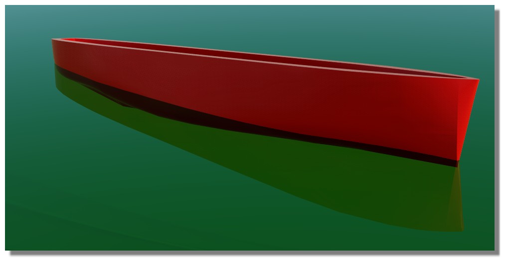
So anyway for give an idea of the volume if you want make a 3D Print for any reasons
you can with your yet made hull make this trick above...
There will only few millimeters height difference between result and optimum wished! (1 or 2 mm)
From: Frenchy Pilou (PILOU)
As now it's a solid you can make any boolean operations you want for simulate the Shell
so
With the super cool free and easy one Simlab Composer Lite! (max 1920 *1080 )
https://www.simlab-soft.com/3d-products/simlab-composer-lite.aspx
From: Michael Gibson
Hi Gord,
re:
> Rebuilt it all now, but used fewer waterlines.
>
> Now I want it as a solid, but the shell offset won't have any of it.
It's the same thing I wrote above (
http://moi3d.com/forum/index.php?webtag=MOI&msg=9819.15):
quote:
Hi Gord, the shell command can only really handle thickening an open surface into a solid if it has all smooth pieces. When there are sharp edges like you have here the surface offsets do not touch each other and would need to be extended and intersected with each other and MoI's shell function is not good at doing that.
Additionally if you have any really tight bends or bumps in it that will be difficult for it to generate an offset surface from as well. An offset surface is generated by moving a distance away from the surface along its surface normal. If the surface normal is wiggling around chaotically it will become magnified in the offset and mess it up.
And also
quote:
3 sided networks can be problematic because the surface generated from it will have one of its sides collapsed down to a point and it is pretty easy for something with bends in it to then have really small tight bends in the collapsed down spot. Instead of a 3 sided network it is usually better to form areas like that by having a larger extended 4 sided surface that then becomes 3 sided by it being trimmed rather than trying to directly construct a surface to those curves. Then a fillet or blend can connect it to the other part.
The 3 sided network on the back has a chaotic wiggly mess at the collapsed tip area here:


The 3 sided network on the front has a chaotic wiggly mess at it's collapsed area too:


If you zoom in very closely to the tip area you can see that it has a lot of bumps and folds in it in a very small area:

Bumps and folds like that means the surface normal is changing wildly in a very small area, that will make the surface offset go crazy there as it tries to build something along the normal. The offset is kind of like taking a stick and sliding it along the surface, any wobbles or folds in the surface get magnified on the offset. So there isn't going to be any chance to get a good surface offset on stuff like that. In general I'd recommend avoiding making 3 sided network, you need to do things like make an extended 4 sided surface and then trim off some area like I wrote about previously here:
http://moi3d.com/forum/index.php?webtag=MOI&msg=9819.15
Your middle 2 pieces are ok, you can separate those out into 2 individual surfaces and use offset on those to get the thickening process going like I described above here:
http://moi3d.com/forum/index.php?webtag=MOI&msg=9819.16
- Michael
Image Attachments:
 gord_3sided1.jpg
gord_3sided2.jpg
gord_3sided3.jpg
gord_3sided4.jpg
gord_3sided5.jpg
gord_3sided1.jpg
gord_3sided2.jpg
gord_3sided3.jpg
gord_3sided4.jpg
gord_3sided5.jpg
From: Gord (NEOMEGA)
Please explain what you did to make it all solid?
I have redone everything, so this is the hull before the decks are cut down.
From: Frenchy Pilou (PILOU)
Pefect just make the same that on my image above!
Create a solid box
Put the boat just a little inside
Boolean Union : you have a solid!
Draw a line any where you want but just under the box
Boolean Diff = you have your Hull solid
And you can now make a Boolean diff between your new hull
and the same hull some scaled
as shown on previous post
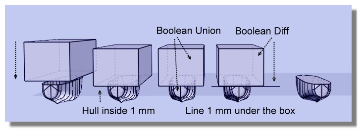
And after you can add 1 mm or more if you want! ;)
Move the face for make the little Shell
But all that because your curves were not perfect from the beginning...
A little shell

From: Frenchy Pilou (PILOU)
Else with your last file!
You can Loft each side one by one
At the bottom deck joint the 2 curves before the last Loft
Delete all curves
Join All surfaces
You obtain a solid! ;)
That don't want say that your deck is a pefect plane and your curves perfect curves! ;)
But you have a perfect solid! ;)

From: Michael Gibson
Hi Gord,
re:
> I have redone everything, so this is the hull before the decks are cut down.
Unfortunately it seems like a step backwards in surface quality. You've now got a lot of separate surface strips that are not smooth to each other:

That's going to make it more difficult to generate offset surfaces to thicken it. You could try thickening it by directly modeling an inner wall instead of using Offset to make it like you could use if the surface quality was better.
The back end still suffers from 3 sided areas that are collapsing to a point while simultaneously trying to go a transition area.

As described above, usually these kinds of transitions are better to do as a separate surface using fillet or blend, rather than trying to construct a surface that tries to negotiate that type of shape change directly.
The triangular collapsed down to a point area here is not quite as chaotic and messy as previous versions, but it will still have problems trying to generate an offset surface from it. Offset surfaces have some general difficulty dealing with pole points where a surface edge collapses down to a single point. That's why I've been recommending over and over again not to try and model the back part this way.
- Michael
Image Attachments:
gord_3rd_try1.jpg
gord_3rd_try2.jpg
From: Frenchy Pilou (PILOU)
If i can give you a little advice :)
Make some training with the method of the Post N°10
https://moi3d.com/forum/index.php?webtag=MOI&msg=9819.10
Like this you will have the good curves, learn to draw curves with the minimum of control Point
(better if you have same number of them by section)
And after you will create your own!
Bon courage!
From: Gord (NEOMEGA)
OK, I understand about doing the stern differently. But how can I get a smooth surface rather than separate strips now? I've realised how to make it all a solid though, so at least some progress is made somewhere!
I realise I'm trying to do something too hard for my meagre skill level though!
Thanks
G
From: Michael Gibson
Hi Gord,
> But how can I get a smooth surface rather than separate strips now?
2 things - you need to have smooth curves and you also need to build it as a larger piece instead of just one sub-section at a time.
See here for some description of why:
http://moi3d.com/forum/index.php?webtag=MOI&msg=1398.18
http://moi3d.com/forum/index.php?webtag=MOI&msg=1398.19
Are the curves that were used to construct that in the file? It seems like there are a couple different sets in there.
- Michael
From: Michael Gibson
Hi Gord, and yes this is a pretty difficult area of modeling, no doubt!
- Michael
From: Gord (NEOMEGA)
Thanks!
I think I need the waterline sections, at least one, to smooth it out. The plan I have to use does not have all the hull lines drawn. I realised a way to do this now.
G
From: Frenchy Pilou (PILOU)
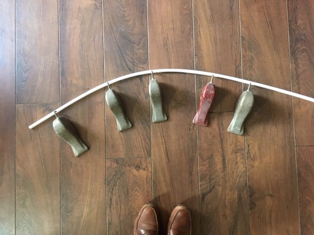
Ok found an image of what i said previously! ;)
You understand with this system that you can't have sharp form! ;)
All is natural smooth line!
From: corchet


pict 1 : to be clear ... a boat with few lines ... and 4 networks to do the external hull
the 2 construction lines at the back can be easily modified ( edit point etc ... )
pict 2 : in yellow .... i copy the lines and do a small scale ( scale 3d - boundary box - type .98 ) 98 percents
i need to align the group of yellow lines on the x axe ( in right view ) so later the bastingage will be horizontal
pict 3 : now i have an external and an internal hull - they need to be joined
pict 4 : the most important !! i draw 4 segments to join the hulls ( i zoom very close for each segment ) to prevent gaps
i select the border of each network patch and do JOIN to be sure to obtain a closed curved ( without that ... no solid later )
when i see Closed curved , i can click separate
pict 5 : the 2 hulls are joined correctly ... select all the faces and join ... now it's a solid wich can support holes and various details
From: corchet
3dm here
From: corchet

peut etre mieux quand c'est moins pointu-tutu ;)
From: corchet
some polygonal modelers like 3dsmax have a shell modifier ( with precision & efficiancy )
you can export a nurbs model with impossible shell ( thru OBJ ) and import for example in max ( c4d or blender ?? ... don't know them )
Max will show you holes on the surface of the shell if the nurbs model has not perfectly joined surfaces
if the shell is correct ... reimport in the nurbs software et voilà
From: corchet


pict 1 : same as precedent stuff ... each patch is verified before network ( join de borders to see Closed curved ) and separate after that
for the 2 missing patches ... select the borders and network
select all the faces and join ... the boat is a solid now
pict 2 : extract the border of the ship and scale ... join ... then rebuild the curve ... extrude and fillet
boolean diff between the ship and the flat piece
pict 3 : fillets and various boolean diff or union etc ...
From: Frenchy Pilou (PILOU)
@Corchet
...ou en rendu pur fixe dans le Free Simlab Composer Light! ;)
https://simlabfr.weebly.com/light.html (here VF)
ou en mouvement dans le vent, la tempête, les embruns, la végétation dans le Free TwinMotion !
(plus tard, là j'ai pas le temps! :(
Semble solide pour affronter la banquise! :)

Can't be floating along the waves...but... :) (of course quality is grandly decreased by the Gif recorder!

From: Gord (NEOMEGA)
The madness continues!
I have now, I think, have a pretty fair hull, not too many lumps ect. I managed to remove the 'starving horse' effect now. But try as I might, I cannot get the stern to attach. I try to make it from a solid, as suggested, but must be doing something else wrong, as I can't get it to fillet at all.
I chopped off the stern and tried adding a planar panel, but this still won't fully joint up. For some reason I have a crack that I can't close. Pulling my hair out again!!
All this is before I try to get it into a solid...
Sorry for being dense! I come to this as a modelmaker, not a computer wiz!
Show messages:
1-4
5-24
25-44
45-64
65-84
85-104
…
125-129