re:
> Thanks. It's because I come from a modelmaking background so will be trying to do things
> as I would in the real world! I'll give that a go.
Yes solids and booleans for mechanical parts matches up pretty well with real world manufacturing with stuff like a cutting tool removing material from stock.
The "skinning mode" type approach doesn't match up so well to real world processes, that's part of why it has a longer learning curve.
OK, pretty pleased how I got it so far with all your help! Now I try adding strakes to the outside of the hull using sweep and profiles with a rail progected onto the hull. It looks like it worked well. Except when I try to join, it won't have anything, but when I try to boolean it on, it simply disappears leaving the profiles and rails.
> Except when I try to join, it won't have anything, but when I try to boolean it on,
> it simply disappears leaving the profiles and rails
So to use Join you can't join something in the middle of another surface, you can only use Join to glue an unattached edge to another unattached edge. So you would need to cut a hole in the hull surface in order to get it set up for Join.
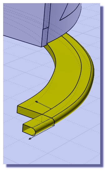
The sweep actually didn't go too well, it's not a solid, it's got a kind of twist in it:
"Yup, that should be possible. But one thing to watch out for is when you make the sweep make the sweep push halfway through or at least a little ways through the hull. Don't make something that has a flat edge that just barely skims right along the same surface area of the hull because such things can be difficult to intersect with booleans."
Your case here is a good example of what I was trying to describe not to do - to set up something that will boolean well, don't make your sweep have a flat edge that is going to make a surface that skims along the hull surface:
That's inside flat piece is close to the hull surface, but it is not going to be exactly the same shape as the hull. It's going to kind of dip in and out of the hull by small amounts and that makes for a really complicated intersection between those surfaces. You need to make the sweep sink in a ways past the hull surface, not have a piece of it that skims right along its surface area.
I think the twist problem with your sweep probably comes from having 2 sweep profiles that have a different number of segments in them. Can you post the curves you used for the sweep so I can check those out?
1 draw lines straight ... polyline with large fillet ... curves etc ... rebuild them
project on the surface and trim ( boat + lines ) and copy paste the 3 lines
2 draw profile for the sweep ... scale it
3 rotate and adjust carefully the position of the profile ( not inside the hull ;)
save before sweep
sweep one on one
4 the third line is not trimmed it turn around the hull so the swwep produce a crap
cut the third line ... mirror it along the boat axe
when you have 2 sweep ... build a round piece with loft and boolean union
each sweeped piece is solid and can be boolean diff with cut line ( the end of the second sweep is bad ... need a cut with an arc placed on top view for example )
I can't replace the third piece on the hull ( scaling manipulation error ... doomdoom )
file joined
( il faut vraiment que j'achete un dico anglais ;) comment avoir plus de 200 mots de vocable dans le parlé de Shak'spire ;)
This thread reminds me of all the problems I had creating Fuselages for Aircraft with nurbs.
Gord
If you haven't already explored this option its worth trying using the loft, loose, exact method. See Andrei's video about 10 minutes in https://youtu.be/WBVUsr-eYdw
The trick with this technique is that all your hull cross section shapes must have the same number of points on them.
After you've lofted the hull shape, you can go back and tweak the points of you splines to create a nice smooth surface that matches your reference images & photos (as closely as possible).
Lofting also allows sharp changing of direction with nurbs without the artifacts and distortion that often occurs when using networks and sweeps.
Sometimes though, swept rails just won't boolean into another solid surface, whereas others had no problem. See the two rails on his one. And why, when you boolean does the object sometimes disappear?
> Sometimes though, swept rails just won't boolean into another solid surface, whereas others had
> no problem. See the two rails on his one.
Similar to how it is difficult to intersect a surface that skims right along another surface area it can also be difficult to have skimming edges like you've got here:
Another problem is in this area where you're trying to boolean there are some microstructures:
It will probably be difficult to do a boolean cut that has to try and intersect through that messy area.
> And why, when you boolean does the object sometimes disappear?
Part of the sequence of doing a boolean is it intersects the 2 objects and then needs to gather well formed closed intersection curve results which it then uses to partition objects into different pieces. If it was not able to get a good closed intersection then it can get confused about how to divide pieces up. The pieces that disappear were being classified as being in the volume that is to be discarded. If there are a lot of little tiny fragments in the area that is being intersected they can get partially glommed together and that can impede getting a well formed close intersection.
So it's not good to do repeated booleans of pieces that are kind of close to being aligned but just a little bit off, that can make those little slivery pieces.
That's basically a problem area to work with since these original hull surfaces didn't align very precisely here like I was talking about earlier above:
This area at the top of that juncture now has problems with edges not meeting up with each other very closely and that kind of loose tolerances will tend to increase "glomming together" in intersections through those spots.
If you're going to be doing more stuff along those joining areas then it's good to get them aligned cleanly from earlier on, it helps to avoid problems further down the road.
OK, thanks. I moved it away from the little parts as it worked. However, on another part, when I boolean, it suddenly deletes the structure for some reason! What happened?
> However, on another part, when I boolean, it suddenly deletes the structure
> for some reason! What happened?
If you post the model I can take a look. It's hard to guess what might be going on without the model.
But it's probably related to those problem spots with micro faces and edges that don't connect to each other very accurately like I was talking about above.