Show messages:
1-12
13-32
33-38
From: Michael Gibson
Hi mk1978,
re:
> Only challenge that I have for construction lines is that I don´t really understand
> what is the best way to offset the construction line.
After you create a construction line if you press and hold on the little tag that appears a menu will pop up and you can pick "Relocate cline" on it, here is a demo:
> Somehow I am not able to define/lock the axis that the construction lines are drawn.
If you want it to go in a world axis direction then make sure "Straight Snap" is turned on in the bottom toolbar:

- Michael
Image Attachments:
 straight_snap_on.jpg
From: Frenchy Pilou (PILOU)
Native Helpers Lines are only straight lines!
So..
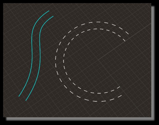
Default of the simulated dashed lines is the physical holes and not the same gap between Offseted curves!
(will be an hard work to have the same gap)
So best is used colored curves as Helpers Lines! ;)
And the Offset is the real Offset! ;)
And can be hide with a simple one click on the toggle "Eye" of the Style Color Browser section! ;)
What do you want more ? :)
From: mk1978
Thanks for all the explanation and videos. My offset challenge is maybe little more simple and it mainly because my Sketchup habits". Here is what I mean with problem to offset the construction line outside of the geometry. In this case (video) it still works fairly ok but if there is more geometry around it has been difficult to define which is the direction that the construction line offset will be created. Naturally it would be great to be able to press for example "arrow up" so that the construction line offset direction would be locked to Z-direction, "arrow left to lock it to X-direction", etc. I am sure that I will get used to this and make it work once I get more experience with MoI.
Anyway, thanks again for great support!
Attachments:
Construction Lines.mp4
From: Frenchy Pilou (PILOU)
For this particular case i will don't use Helper lines!
Draw and Move a simple square will be many more speed! ;)

From: Michael Gibson
Hi mk1978 yeah for that particular type of usage I probably wouldn't use construction lines. I'd probably just use object dragging. First drag it to align with the reference point, then drag 2 more times using distance constraint. You can enter in your distance constraint for an object drag by typing in a value and pushing enter before doing the drag, like this:
Or if you know the displacement in the x and y directions you can use the Transform > Move command instead of the last 2 drags and enter in a relative coordinate value for the second move point by typing rx,y, so for example type r-10,-10 to move by -10 in x and -10 in y from the first picked point in Transform > Move.
If you like to visualize the target point by an offset outline, then another possibility would be to use the offset command to build some temporary geometry, then you only need to enter one offset value. And you also can then just drag the object into place instead of using the Transform > Move command:
- Michael
From: mk1978
Do you know what is the reason why I am not able to execute Shell command on this part?
I would assume that the problem is with the curve that has been used for creating the face but is there something that can be done to clean the curve, etc.?

Attachments:
ShellTest.3dm
Image Attachments:
Capture.JPG
From: Phiro
Hi,
your model is super huge.
Perhaps do you not see the shell because of the size.
I test the shell after having resize and I had no problem.
In the screenshot, Is it the face you want shell ?

Image Attachments:
Capture.PNG
From: Phiro
You could have a limit in shell with the corners.
Shell could erase te small face and it is impossible for MOI.

Image Attachments:
Capture2.PNG
From: Michael Gibson
Hi mk1978, same as Phiro over here - shell is working on your object as long as you stay under a thickness that would cause the area shown above to collapse in on itself. That's around 170 units or so.
What thickness value are you trying to use?
- Michael
From: mk1978
I have been trying to use 200mm thickness. Now it works perfect, thanks again for help for both!
From: bemfarmer
First time I've ever used the construction line tag.
Is it possible to make the tag bigger?
It is really small on Hi-Def monitor.
- Brian
From: Michael Gibson
Hi Brian,
re: make construction line tag bigger - the size of that comes from the image MenuLauncherTag.png in the ui sub-folder. If you increase that image size it should increase in the UI as well to match.
I've been thinking of maybe getting rid of that thing and having a "Construction line" section appear on the side pane when you make one instead.
- Michael
From: bemfarmer
Thank you Michael, I'll try out a larger png. I think W10 power tools has a sizer.
Sidepane section might be good, especially for those of us who do not read all of the documentation :-)
- Brian
From: mk1978
Again some more questions to understand Moi3D better.
1. Do you know what is the reason why I am not able to perform Union command in this shape? I have been using Boolean / Union but somehow I am not able to combine these solids. Moi3d example file attached.
2. When extruding the form is this (arrow) only visible error or do you think that there is something wrong with the curves that I am using?

Attachments:
ExtrusionTest.3dm
Image Attachments:
Union_Extrusion.JPG
From: corchet

your object has huge dimensions - 10000 etc
i rescale
apply join and rebuid on all your curves
extrusions and union are ok ( 3dm attached )
From: mk1978
Thanks for the tip! I always forget that the size may be causing some challenges.
From: Frenchy Pilou (PILOU)
You can also add some volumes thickness on some faces of one volume
for not have just "flat" intersection surfaces when you have some complex volumes...
From: corchet
my bad i forget the subtracted piece
From: Michael Gibson
Hi mk1978, it tends to be more difficult for the booleans to process objects that have overlapping surface areas, it makes for a more complex intersection.
It can work though if the pieces are accurately placed. In your your case here things are off by a bit:


Like corchet mentions above, it's also not so good to have large coordinate values for your objects like having it 10000 units across.
In the attached file, I scaled your objects down by 1/100 in size so they don't have overly large coordinate values and I also just moved your pieces so they were accurately in place and now the boolean should work ok.
- Michael
Attachments:
ExtrusionTest2_3dm.zip
Image Attachments:
mk_bool1.jpg
mk_bool2.jpg
mk_bool3.jpg
mk_bool4.jpg
From: mk1978
Thanks for the comments Michael. It seems that I have made small errors when editing/mirroring parts so it is good to understand that these are causing the problem. Naturally it is difficult to spot these because the model/parts are huge in size.
Show messages:
1-12
13-32
33-38