I have been modeling over 10 years with a Sketchup and I am nowadays 3d printing many of my 3d modeled parts. This is the reason why I would like to have a better tool to create 3d printed parts (fillets, boolean, etc.).
I have been watching Moi3D YouTube tutorials and I just downloaded the trial version of the Moi3D. What would be the basic logic to model this kind of part in Moi3D? I am so stuck with Sketchup thinking that I have not been able to figure out how to model the basic shape and still be able to fillet edges.
In Sketchup I would probably:'
-Model the bottom shape
-Extrude half way up (to get the edge in the centre)
-Extrude to the top
-Scale the edge in the centre
-Fillet the edges to get nice 3d print (Sktchup has some limitations in this)
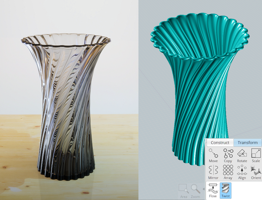
My first thought was to use a Loft to make the vase.
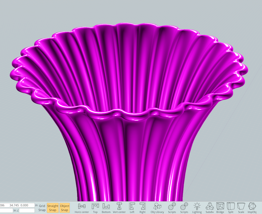
However, I think a Rail Revolve will give you the greatest control over the design, especially how the fillet is formed on the top edge.
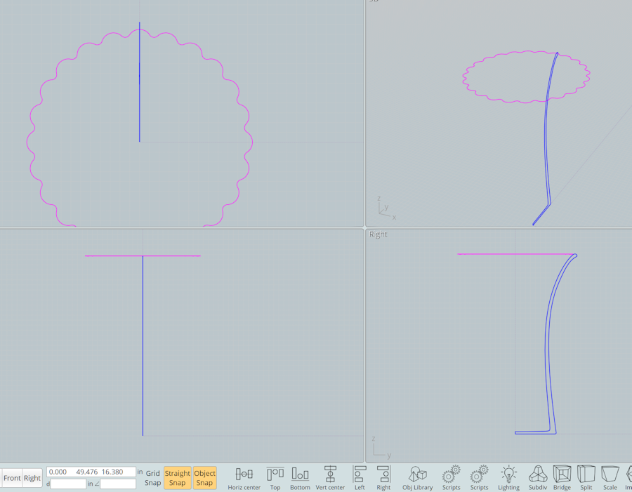
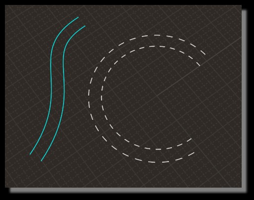
Start by making the "Rail" for the Rail Revolve:
Create two circles. Circular Array the small circle around the large circle. Select all circles and Boolean Union. Select the result and Fillet.
If you want the interior flutes to be reduced, just offset your small circle toward the inside of the larger circle before performing the circular array.
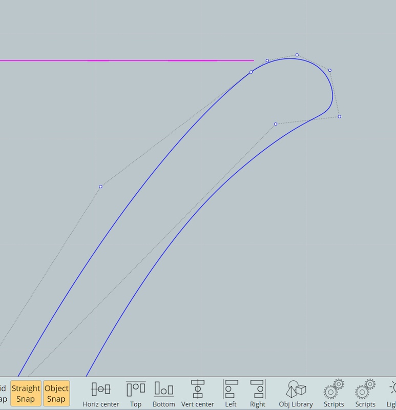
In Right View, draw a closed Profile Curve (shown in blue). Notice how the rounded top edge flares out just a little.
Want thicker walls or a thicker bottom? Just select the points on your the profile curve and edit as needed.
Profile curve upper edge detail:
Rail Revolve the blue "profile" around the magenta "rail". (Don't select "Cap Ends). The result is a solid vase. Output as a STL file and you're ready to print!
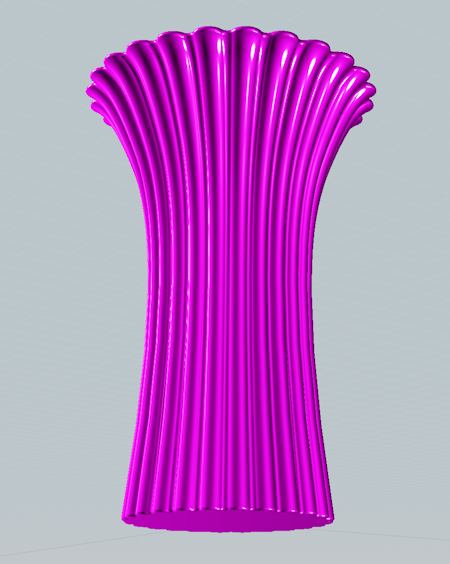
You can even select the result and give it a Twist:
re:
> This is what I have been trying to model in Moi3D
Well from a glance it does not necessarily look like you couldn't do it that way with lofting. Could you post your .3dm model file so I can take a look at what you've got?
Here's a different method though using a sort of "structured drawing" approach.
With this method you temporarily ignore the wavy shape and instead focus on a base underlying surface form. The Revolve tool can be good to make a cylindrical type shape like that.
So a 2D profile curve like this:
Then Construct > Revolve, with the revolve axis along the open ends:
So that's all you need to make the base shape, just one profile curve and one command. This is kind of what you want to be shooting
for with NURBS modeling, I mean making large simple chunks of your model out of a small number of 2D profile curves.
So now to make it wavy. I thought it would be good to put in a tube and use boolean difference to cut out grooves. I initially tried
making a tube using Sweep but I found that you don't want a regular tube because you want the grooves to shrink down
in the narrow waist area and expand in the top.
You could put in several profile curves for a sweep with some smaller and some larger to make a tube like that, but a more
convenient way is to use the Transform > Deform > Flow tool which can map an object from a base plane onto curved surface. It
will also expand or shrink as the target surface expands or shrinks.
So to do that I drew in a base plane and a cylinder on it and used Transform > Deform > Flow
(more info on it in the help file here: http://moi3d.com/3.0/docs/moi_command_reference8.htm#flow)
to produce a tube that hugs the outer surface and also expands or contracts with it. Also the position of the cylinder above or below the
plane will control how the tube sits on the curved surface so I moved the cylinder upwards a little so that a smaller zone of it
is embedded down into the curved surface:
Next use Transform > Array > Circular to replicate the tube around in a circle pattern. It's probably going to be good for filleting to make enough copies so that the tubes eat away all of the original outer surface:
Then use Boolean difference to cut the base shape with the tubes:
Select the edges that have been formed by the intersection between tubes:
And run Fillet on those with a large-ish fillet radius:
Now the whole object can be selected and do another fillet with a smaller fillet radius:
Re:
Well from a glance it does not necessarily look like you couldn't do it that way with lofting. Could you post your .3dm model file so I can take a look at what you've got?
Here is the file that I was testing, see attachement. I have not been able to fillet the part but it must be because I am still having some problems to understand the different logic when modeling with nurbs.
Thanks for everybody for all the tips! I was not really expecting this many tips with such a detailed instructions. I need to do some more testing this weekend!
This is what I have been able to model so far. I have actually "lifted the top up" in the top and the plan is to create some holes (circular array) to place some artificial flowers on it.
So it looks like the problem with filleting your shape on the right is that you have 2 loft sections that have sharp corners in them:
Then for the top profile curve of the loft it has a different shape, there the curve segments are smooth to each other instead of sharp like the lower 2 sections:
This is not a good situation for filleting, basically because a fillet is something that goes on a sharp edge.
Check out this example here where I've got 2 surfaces that vary in angle to one another, starting at 90 degrees to each other and then progressing to being almost smooth to each other:
If you make a fillet between there it will look like this:
So note there that the fillet starts out wider and then gets narrower and narrower as the surfaces become closer to being tangent to each other. If the surfaces became completely smooth to each other then the fillet would shrink down to 0 width at that spot and that makes things a lot more difficult for the fillet construction.
Also that above is not what is called a "variable radius fillet" - it's a constant radius fillet. What is changing there is the length of the arc for that spot in the fillet. They are all arcs of the same radius, just some are long and some are shorter length arcs. Here is another example this time with curves showing how it works as you go from a larger angle to an almost smooth angle. These are all the same radius circle but you can see that the piece of the circle that will be used gets shorter as the tangent directions approach being smooth:
Then there's also a fillet mechanism called "variable radius" fillets - that's where the radius of the fillet arc is also changing as you travel along the fillet. That will also make for variations in the width of the fillet but in a different way.
So for filleting to have a better chance to work well you would want to avoid this kind of "sharp segments, sharp segments, smooth segments" progression between your loft profiles. If you had made them all the same sharpness like your ones in the middle, then you would be able to fillet it ok:
I am still learning Moi3d and I would like to again as some help with modeling logic because I am so stuck with Sketchup way of modeling.
Is there a way to create "Sketchup components or Groups" in Moi3D. For example if I have 4 tires or bolts in the model and I would edit one of the tyre it would modify also the rest of the tires in the model. In addition, is the are way to move the items as a Group for example creating an individual group for multiple Objects and moving all the Objects at the same time? Or how do you deal with this kind of items?
Are there some video tutorials how to use the Construction lines? I have been reading Command reference document but it is not clear to me for example how to offset construction lines.
Hi mk1978, MoI does not currently have that type of "instancing" function like SketchUp components but it is something I want to add in the future.
For moving a set of objects all at the same time, if the objects are all selected then they will move together at the same time when you drag them or use Transform > Move. If you are repeatedly selecting the same set of objects you can assign them a name and then that name label will appear in the Scene Browser and you can select them with one click there.
> Are there some video tutorials how to use the Construction lines? I have been reading
> Command reference document but it is not clear to me for example how to offset construction lines.
I don't think there is a video, but if you want to make a construction line and then move it somewhere else you can use the "Relocate cline" option on the construction line pop up menu that is shown in the command reference. To move it by a set distance set the "distance constraint" value in the bottom toolbar.
If you can maybe sketch out an example of the situation where you want to use it I can make an example video for you.
Thanks for these links I don´t understand any french but these are anyway very helpful. The construction lines scripts are also great. Only challenge that I have for construction lines is that I don´t really understand what is the best way to offset the construction line. Somehow I am not able to define/lock the axis that the construction lines are drawn.
I will take a look of the Elephant nodal system later this week. It is good to know that there could be some help for this instancing challenge also.
re:
> Only challenge that I have for construction lines is that I don´t really understand
> what is the best way to offset the construction line.
After you create a construction line if you press and hold on the little tag that appears a menu will pop up and you can pick "Relocate cline" on it, here is a demo:
> Somehow I am not able to define/lock the axis that the construction lines are drawn.
If you want it to go in a world axis direction then make sure "Straight Snap" is turned on in the bottom toolbar:
Default of the simulated dashed lines is the physical holes and not the same gap between Offseted curves!
(will be an hard work to have the same gap)
So best is used colored curves as Helpers Lines! ;)
And the Offset is the real Offset! ;)
And can be hide with a simple one click on the toggle "Eye" of the Style Color Browser section! ;)
What do you want more ? :)
Thanks for all the explanation and videos. My offset challenge is maybe little more simple and it mainly because my Sketchup habits". Here is what I mean with problem to offset the construction line outside of the geometry. In this case (video) it still works fairly ok but if there is more geometry around it has been difficult to define which is the direction that the construction line offset will be created. Naturally it would be great to be able to press for example "arrow up" so that the construction line offset direction would be locked to Z-direction, "arrow left to lock it to X-direction", etc. I am sure that I will get used to this and make it work once I get more experience with MoI.
Hi mk1978 yeah for that particular type of usage I probably wouldn't use construction lines. I'd probably just use object dragging. First drag it to align with the reference point, then drag 2 more times using distance constraint. You can enter in your distance constraint for an object drag by typing in a value and pushing enter before doing the drag, like this:
Or if you know the displacement in the x and y directions you can use the Transform > Move command instead of the last 2 drags and enter in a relative coordinate value for the second move point by typing rx,y, so for example type r-10,-10 to move by -10 in x and -10 in y from the first picked point in Transform > Move.
If you like to visualize the target point by an offset outline, then another possibility would be to use the offset command to build some temporary geometry, then you only need to enter one offset value. And you also can then just drag the object into place instead of using the Transform > Move command:
Do you know what is the reason why I am not able to execute Shell command on this part?
I would assume that the problem is with the curve that has been used for creating the face but is there something that can be done to clean the curve, etc.?