From: twofoot
Hi folks. While I have been a Moi user for many years, I am not the greatest designer of organic shapes. I would like to build a large scale, ride on model of this locomotive, and plan to 3D print the nose section. Unfortunately, I can't get the forward section of the locomotive drawn correctly in 3D space. The "bulldog" shape of the nose is very distinctive and recognizable, and I want it to be as close the the prototype as possible.
Can anyone offer help, guidance, or suggestions? Thank you!
Chris
From: bemfarmer
Load image into MoI, and trace various 2d profile curves.
Pictures show left, frontal, and top view.
If a curve is not a standard circular arc or ellipse, short tangent lines can be manually placed, and a blend curve formed between them.
(The clothoid can also be used, with the end tangents slider adjusted.)
- Brian
From: ed (EDDYF)
Chris –
Here’s how I would model the locomotive cab:

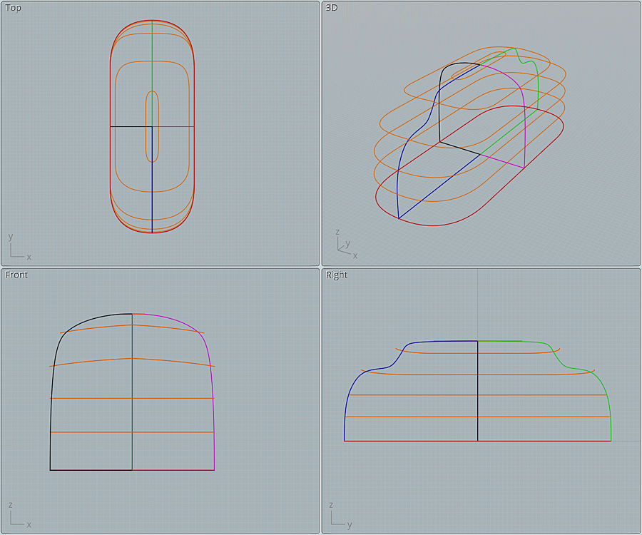
That type of transition in the area when the windshield meets the side window is complex, so I’d begin with a symmetrical network as shown.
The red base is a closed curve. The blue & green open curves are mirrors. The black and magenta open curves are mirrors. Notice how the 4 curves meet at a single point at the top, and again at the bottom. The 4 corners must touch the base red closed curve. All of these curves are based on the 2D drawings of the locomotive.
The orange closed curves are copied, resized, versions of the red base curve. They don’t have to touch the other curves, but they need to be close. I call these “influencers” or “helper curves”.
In front view, notice the two orange curves near the cab window area. Those are curved upward to create an arch in the cab's window and roof line.
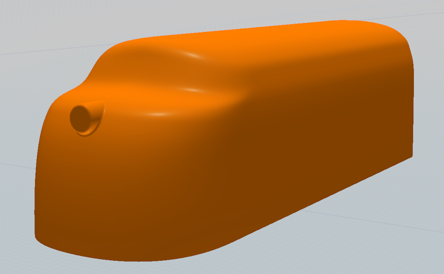
After selecting all the curves and performing Network (Mode: Lighter), you can move and size the orange “influencers” (using their boundary box handles) and watch the network change shape. After some adjustments you can get a fairly smooth result. The resulting network is a solid.

After the curves are Networked, draw a straight line just behind the cab and Boolean Diff. Then select the planar surface at the back of the cab and Extrude it to the length of the locomotive. Select both solids and Boolean Union.
Next add a cylinder for the headlight, Boolean Union with the loco, and Fillet.
The finished locomotive is a solid and should output as a STL for 3D printing with no problem.
Note: After re-reading your post I see you're going to 3D print a large scale version of just the cab shell. So I would Network the curves as a Surface, rather than as a Solid. To do so, Trim away the 4 bottom straight line segments that meet up at the base. Select all the curves and perform Network (Mode: Lighter). Then Trim the resulting surface so you have just the forward cab, and trim it again in half. Then Shell the two half's separately. Dice it up from there into smaller pieces that will fit on your printer.

Whatever method you use to model this, I'd love to see photos of your project as it progresses.
Looking at the photos more closely, it appears the headlight housing is a bit more integrated with the cab than what a simple Fillet will accomplish. I think some additional work using Blend is needed. But to quote my high school math book, "That is an exercise left to the reader" :)
Good luck, and hope this gets you on the right track :)
Ed Ferguson
From: Frenchy Pilou (PILOU)
Very cool tuto!
How was the designer ? Raymond Loewy ?
A cool link
https://www.pinterest.co.uk/pin/44191640070358882/
Seems there is your on the left side after some scrolling! ;)
From: twofoot
Thanks Ed, and to everyone who offered assistance. This should get me going in the right direction.
Chris