Show messages:
1-9
10-29
From: Michael Gibson
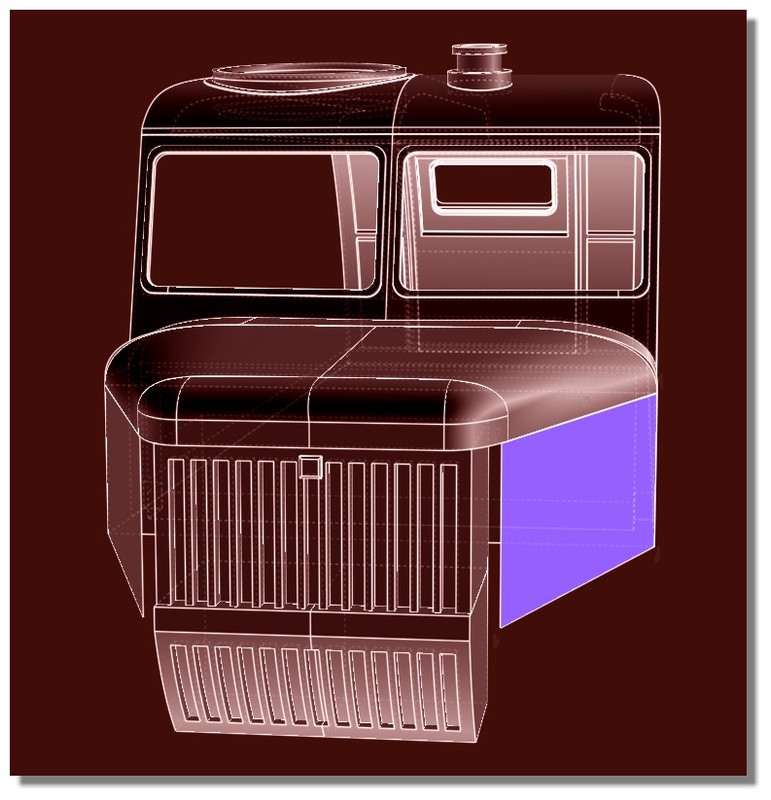
A good way to put in rounded corners on the curves is to have a plain sharp cornered rectangle to start with and then use curve fillet to round the corners.
- Michael
From: Michael Gibson
So probably a good way to do these would to only have one profile curve (make it a rectangle and put rounded corners on it with curve fillet), and use it to boolean a hole. Then do a sweep like this:

These pieces should match up very well now and you can then use boolean union to combine them together, see attached 3dm file.
- Michael
Attachments:
 gord_window.3dm
Image Attachments:
gord_sweep.jpg
From: Gord (NEOMEGA)
Can you add a planar to a curved surface? I can't fill it in.
From: Frenchy Pilou (PILOU)
Planar just Fills plane holes!
For a cuvated surface you can for example make that...alligne the Control Points...then fill them if holes existing...
From: Gord (NEOMEGA)
Ahh! Pulling my hair out. I have it made by trimming then extruding the surface. Now it won't join up when I boolean it!
G
From: Frenchy Pilou (PILOU)
Better to redraw...seems you have overlaping curves ;)
- Draw the box
- Draw the external outline on the box (Rectangle + Fillets)
- Draw the internal Offset
- Boolean Diff Box / Internal Offset = Solid 1
- Draw the arc curve Profil
- Sweep
- Planar the "Offsets" (for security to see 2 solids...)
- Join the 2 Surfaces = Solid 2
- Kill curves
- Boolean Union Solid 1 + Solid 2 = one solid :)
With training in less 60 seconds you will keep your hairs! :)
It's that i made...no special problem! :)
From: Michael Gibson
Hi Gord, your main object is not a solid and so you won't be able to use a boolean on it. Booleans are primarily for working on solids, they use which part of the solid that a piece is contained inside of to determine which pieces to keep and which pieces to discard.
When your base object is not a closed solid it won't be able to determine such things. So on an open surface you will usually need to use the Edit > Trim followed by Edit >Join command rather than a boolean command. Basically a boolean is a sort of "batch mode" operation that internally does Trimming and joining with it automatically deciding what pieces to discard based on volume containment.
When you have open surfaces you will need to use the lower level approach instead of the "batch mode" approach.
So as described earlier in order to use Edit > Join you need to have pieces that touch at unjoined edges.
Your extruded surface is a solid so you'll first need to delete its bottom cap to give it a place to join.
To do that, select your extruded surface and right-click on the Edit > Hide button to isolate that object and make it easier to work on it. Your screen should look like this now:

Rotate your view so that you are looking at the underside of that object. Then select the bottom cap and delete it:


After deleting that bottom face you now have unjoined edges that can be joined to other surfaces where they touch.
Now right click on the Edit > Hide button again to do an "unisolate" and restore things to their pre-isolate state.
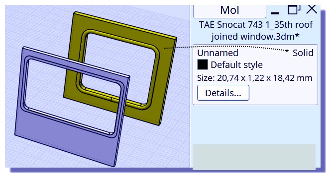
Now when I zoom in to look at how things meet up I can see that your extruded solid is positioned half in and half out of your other surface, not touching it edge to edge. This probably is a result of extruding with the "Both sides" option enabled which you probably didn't want to have turned on.

So I dragged the ring upwards so that it does touch edge-to-edge with the other surface and then used Edit > Join to get the attached 3dm result.
- Michael
Attachments:
gord_joined.3dm
Image Attachments:
gord1.jpg
gord2.jpg
gord3.jpg
gord4.jpg
From: Gord (NEOMEGA)
Many thanks! I'll have to try this. I have done it now by extruding the surface as advised.
I'm very new to CAD. I'm a professional modelmaker and am trying to make it do things in a way I'd make them by hand. Not so easy!
Tx
G
From: Frenchy Pilou (PILOU)
Just draw your curves with precision! ;)
From: Gord (NEOMEGA)
Many thanks. However, you lost me at Planar the offsets part. I have a managed to do it though.
However, I now have a more challenging version. I need the same thing doing again, but this time it's on a curved surface!
Please explain this as though you are talking it through with your mother... I do have a degree, it just it's not in anything computer or CAD-like! Sometimes people think you have some basic knowledge so assume they understand and skip bits they think are obvious.
Thanks again
Gordon
From: Frenchy Pilou (PILOU)
Planar the offsets part = create a plane surface between the 2 OffSeted parts! ;)
Kill the curves (Profil, rounded rectangles) Join the 2 Surfaces = Solide 2
Here just the Planar function :)
From: Michael Gibson
Hi Gordon,
re:
> However, I now have a more challenging version. I need the same thing doing again, but this time it's on a curved surface!
If you can post the .3dm file with your surface and curves in it that would help to make suggestions. Also it tends to be easier to understand if you export out just the pieces relevant to this particular operation.
- Michael
From: Michael Gibson
Hi Gordon,
re:
> I'm very new to CAD. I'm a professional modelmaker and am trying to make it do things
> in a way I'd make them by hand. Not so easy!
It seems like you're off to a good start! Keep at it and it will keep getting a little easier.
Like Pilou mentions above, probably the #1 tip is to make sure your starting curves are well constructed and don't have any anomalies in them. Anything messy about the curves will tend to inherit to stuff constructed from them as well.
- Michael
From: Gord (NEOMEGA)
Super job, thanks!
G
From: Gord (NEOMEGA)
Hi.
Apologies again!
It seems now that most of this model is made up from surfaces and not solids as I wanted. Is there a way to turn them back into solid or have I to start again after 10 days of effort? Will it print like this?
Thanks
G
From: Michael Gibson
Hi Gordon, you need to have solids for 3D printing. Are you going to want to print the whole thing in one piece or are you planning on printing it as several parts?
You don't necessarily have to start over if you don't have solids, you can convert an open surface into a solid by using Edit > Join to glue in surfaces to fill in open spots.
If some areas are open because pieces are missing then that means you would need to construct new surfaces there. If some areas are open because pieces did not meet up very cleanly then it may involve redoing those areas.
To figure out why an object is not a solid, set up the shortcut key as described here:
http://moi3d.com/forum/index.php?webtag=MOI&msg=6051.2
Then you can push a shortcut key and see where the "naked edges" are at, those are spots where an edge belongs to only one surface instead of being joined between 2 surfaces like you need for a solid.
- Michael
From: Frenchy Pilou (PILOU)
for 3D print something today each objects must be "solid" and "waterproof"...
There is something possible but that is not fair! :)
Save as Obj and reload it in a "Voxel" program so all becomes "solid" because that will be only "cubes" ;)
A free cool one is Magicavoxel...a not free is 3D Coat...
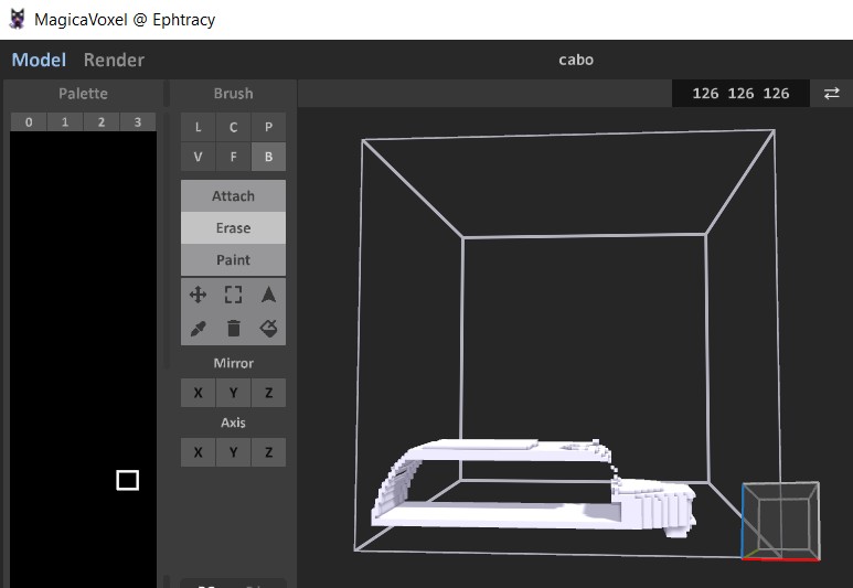
But the game here is to made it in Nurbs with Moi ! ;)
So just take object by object and search the one(s) who is (are) not "solid" !
From: Gord (NEOMEGA)
Thanks!
The thing will be split into several components. So I can if I have a hollow part, say without an end on it, I can patch in a surface and join it to the other sides then?
Tx!
G
From: Frenchy Pilou (PILOU)
You must not have surfaces without thickness!
This never works! Surface(s) must made a volume! A surface alone makes nothing for 3D print!
From: Michael Gibson
Hi Gordon,
re:
> So I can if I have a hollow part, say without an end on it, I can patch in a surface
> and join it to the other sides then?
Yes that's correct. For some areas like the open bottom here:

those could probably be avoided by getting your object to be a closed solid before you applied the cut to it. If you cut a solid with a boolean operation, it will leave behind the imprint of the cutting object to fill those areas in right then so you don't have to do it separately.
See these for some description of this:
http://moi3d.com/forum/index.php?webtag=MOI&msg=8822.15
http://moi3d.com/forum/index.php?webtag=MOI&msg=7102.3
http://moi3d.com/forum/index.php?webtag=MOI&msg=5075.3
http://moi3d.com/forum/index.php?webtag=MOI&msg=3883.3
The way to fix up something like this manually is you would get the surfaces used to cut the object:

Then select those bottom surfaces, run Edit > Trim and pick the upper object as the cutting object. Then inside the Trim command pick this region as the area to discard:

That will leave this remaining piece which is then what you need to join in there:

These steps could probably be avoided though if you could close off the object to be a solid earlier on before cutting it.
- Michael
Image Attachments:
gord_bottom.jpg
gord_bottom2.jpg
gord_bottom3.jpg
gord_bottom4.jpg
Show messages:
1-9
10-29