Show messages:
1-20
21-29
From: Gord (NEOMEGA)
I'm trying to work out how to get a raised circular flange effect on a 2 way curved surface. I can get the Project Curve bit to show, and can extrude that, but it's only the sidewalls. I can't get it to become solid. Planar won't work on the curved circle either.
Probably an easy one, but I'm stumped!
Thanks!
Gordo
Image Attachments:
 Screenshot 2020-01-19 at 15.47.36.png
Screenshot 2020-01-19 at 15.47.57.png
Screenshot 2020-01-19 at 15.47.36.png
Screenshot 2020-01-19 at 15.47.57.png
From: Frenchy Pilou (PILOU)
Maybe like that...
Make a Cylinder at the height wished
Boolean Union
Then Trim and modelise as you want your Cylindrical object
...and better to post your actual file 3dm with problem!
...else you can close an inclined circular surface with Construct / Nsided with Bulge = 0
(just trim the perimeter for have several edges continuous
and don't make the trim on the generator circle! )
etc...
From: Michael Gibson
Hi Gordo, so when you extrude a curve it will only get end caps if the curve is closed and also planar. But you can also extrude a surface instead of a curve and when you do that it will get capped.
So probably try something like trim your surface with your curve (you don't need to project it as a separate step, Trim can do projection built into it) so that you have a small surface fragment and then extrude that surface fragment.
Check out here for some links to examples:
http://moi3d.com/forum/index.php?webtag=MOI&msg=9335.2
Let me know if that isn't what you needed.
- Michael
From: Gord (NEOMEGA)
Many thanks, I'll give it a go.
I now encountered another one. Try as I might, I cannot get some elements to join or boolean together. The surfaces all seem to touch but it fails every time.
I enclose the file to see where I went wrong.
Thanks
Gordo
From: Frenchy Pilou (PILOU)
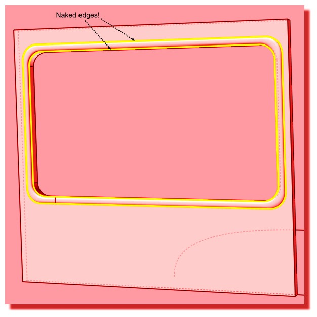
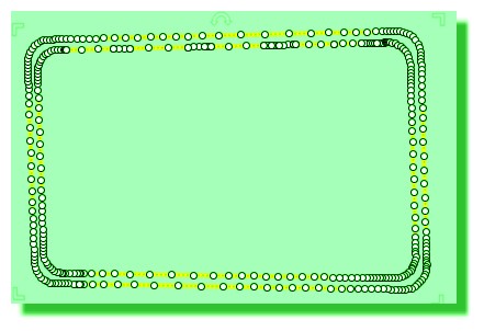
Seems for any reason you have "Naked edges" on your windows objects something is wrong on the Paths of the window!!
so solids can't be created!
<< a "Naked edge" is an edge that belongs to only one surface instead of where 2 surfaces are joined together.
<<The main use for identifying these is if you're trying to make your object into a closed solid. A closed solid needs to have all joined edges and no naked edges.
<< Also even if you're not making a solid it can help to identify if there are unwanted gaps in any areas.
script: /* Naked Edges */ var gd = moi.geometryDatabase; gd.deselectAll();
var breps =gd.getObjects().getBreps(); for ( var i = 0; i < breps.length; ++i )
breps.item(i).getNakedEdges().setProperty( 'selected', true );
From: Michael Gibson
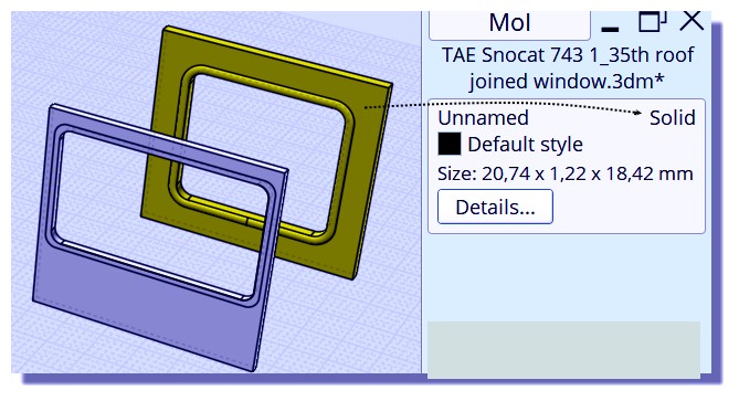
Hi Gord, is it these 2 pieces here that you were trying to join? :

If so the reason you can't join those is the larger block is a closed solid, it does not have any unjoined edges in it. You can only Join pieces that are touching each other at unjoined edges.
You would need to delete a face of that closed solid to make it have unjoined edges and then that's where it can be joined if it matches close enough.
But also there appears to be a really skinny slivery extra surface in this area here:

That will also probably mess up joining, that degenerate surface will probably need to be removed for it to be able to join ok.
- Michael
Image Attachments:
gord_join1.jpg
gord_join2.jpg
From: Gord (NEOMEGA)
Thanks!
G
From: Michael Gibson
Hi Gordo, there is also additionally a bit too much of a gap between the surfaces in this area:


That's a little more than a 0.005 unit gap between there, and that's just very slightly more than the join tolerance. Join will only join pieces that are less than 0.005 units apart from each other.
The rounded surface might be good to build differently, if you turn on its surface control points you can see they are pretty slanted in some areas:


- Michael
Image Attachments:
gord_join3.jpg
gord_join4.jpg
gord_join6.jpg
gord_join7.jpg
From: Michael Gibson
Some of the problems come from these construction curves, they don't quite match up right in this spot, they overshoot a bit:


- Michael
Image Attachments:
gord_overshoot1.jpg
gord_overshoot2.jpg
From: Michael Gibson
A good way to put in rounded corners on the curves is to have a plain sharp cornered rectangle to start with and then use curve fillet to round the corners.
- Michael
From: Michael Gibson
So probably a good way to do these would to only have one profile curve (make it a rectangle and put rounded corners on it with curve fillet), and use it to boolean a hole. Then do a sweep like this:

These pieces should match up very well now and you can then use boolean union to combine them together, see attached 3dm file.
- Michael
Attachments:
gord_window.3dm
Image Attachments:
gord_sweep.jpg
From: Gord (NEOMEGA)
Can you add a planar to a curved surface? I can't fill it in.
From: Frenchy Pilou (PILOU)
Planar just Fills plane holes!
For a cuvated surface you can for example make that...alligne the Control Points...then fill them if holes existing...
From: Gord (NEOMEGA)
Ahh! Pulling my hair out. I have it made by trimming then extruding the surface. Now it won't join up when I boolean it!
G
From: Frenchy Pilou (PILOU)
Better to redraw...seems you have overlaping curves ;)
- Draw the box
- Draw the external outline on the box (Rectangle + Fillets)
- Draw the internal Offset
- Boolean Diff Box / Internal Offset = Solid 1
- Draw the arc curve Profil
- Sweep
- Planar the "Offsets" (for security to see 2 solids...)
- Join the 2 Surfaces = Solid 2
- Kill curves
- Boolean Union Solid 1 + Solid 2 = one solid :)
With training in less 60 seconds you will keep your hairs! :)
It's that i made...no special problem! :)
From: Michael Gibson
Hi Gord, your main object is not a solid and so you won't be able to use a boolean on it. Booleans are primarily for working on solids, they use which part of the solid that a piece is contained inside of to determine which pieces to keep and which pieces to discard.
When your base object is not a closed solid it won't be able to determine such things. So on an open surface you will usually need to use the Edit > Trim followed by Edit >Join command rather than a boolean command. Basically a boolean is a sort of "batch mode" operation that internally does Trimming and joining with it automatically deciding what pieces to discard based on volume containment.
When you have open surfaces you will need to use the lower level approach instead of the "batch mode" approach.
So as described earlier in order to use Edit > Join you need to have pieces that touch at unjoined edges.
Your extruded surface is a solid so you'll first need to delete its bottom cap to give it a place to join.
To do that, select your extruded surface and right-click on the Edit > Hide button to isolate that object and make it easier to work on it. Your screen should look like this now:

Rotate your view so that you are looking at the underside of that object. Then select the bottom cap and delete it:


After deleting that bottom face you now have unjoined edges that can be joined to other surfaces where they touch.
Now right click on the Edit > Hide button again to do an "unisolate" and restore things to their pre-isolate state.
Now when I zoom in to look at how things meet up I can see that your extruded solid is positioned half in and half out of your other surface, not touching it edge to edge. This probably is a result of extruding with the "Both sides" option enabled which you probably didn't want to have turned on.

So I dragged the ring upwards so that it does touch edge-to-edge with the other surface and then used Edit > Join to get the attached 3dm result.
- Michael
Attachments:
gord_joined.3dm
Image Attachments:
gord1.jpg
gord2.jpg
gord3.jpg
gord4.jpg
From: Gord (NEOMEGA)
Many thanks! I'll have to try this. I have done it now by extruding the surface as advised.
I'm very new to CAD. I'm a professional modelmaker and am trying to make it do things in a way I'd make them by hand. Not so easy!
Tx
G
From: Frenchy Pilou (PILOU)
Just draw your curves with precision! ;)
From: Gord (NEOMEGA)
Many thanks. However, you lost me at Planar the offsets part. I have a managed to do it though.
However, I now have a more challenging version. I need the same thing doing again, but this time it's on a curved surface!
Please explain this as though you are talking it through with your mother... I do have a degree, it just it's not in anything computer or CAD-like! Sometimes people think you have some basic knowledge so assume they understand and skip bits they think are obvious.
Thanks again
Gordon
From: Frenchy Pilou (PILOU)
Planar the offsets part = create a plane surface between the 2 OffSeted parts! ;)
Kill the curves (Profil, rounded rectangles) Join the 2 Surfaces = Solide 2
Here just the Planar function :)
Show messages:
1-20
21-29