Show messages:
1-5
6-25
26-45
46-54
From: mdesign
Thanks.
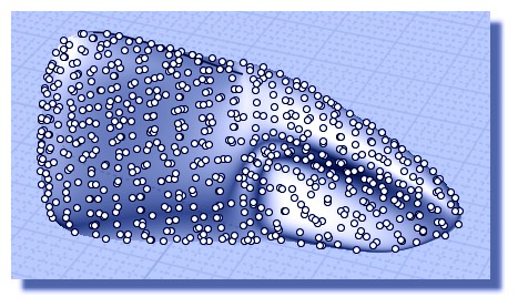
I`ve thought about distributing points over the surface similair to SpherePts but over the surface to do some cells/grid over complicated mesh.
From: James (JFH)
mdesign,
There is no convert surface to points node, instead you first convert surface to isoCurves then convert these to point arrays as shown below.
It is important to note that this will only work with surfaces bound by 4 edges.
Hope this helps...I look forward to seeing what you get up to with NE.
Please don't hesitate to asks for help if you get stuck.
James
https://www.instagram.com/nodeology/

Image Attachments:
 Screen Shot 2019-10-30 at 7.21.gif
From: Michael Gibson
Hi mdesign, so to add a shortcut key you need to use the Options dialog in MoI to do that. There you're editing the properties of the Windows shortcut used to launch MoI.
In MoI click the Options button on the bottom toolbar, and then in the Options dialog there is a section for " Shortcut keys":

- Michael
Image Attachments:
mdesign_shortcut_keys.jpg
From: James (JFH)
Michael,
Following on from mdesign's question about points on a surface:
http://moi3d.com/forum/index.php?webtag=MOI&msg=9547.4
It is my understanding that the points displayed with "show pts" function are not addressable by scripting (or with nodes) because they do not have unique identification. Is that right?
Would it be a difficult task to tag each with random identifier so that a surface or curve may be manipulateded, say for example with Points/movePts node, without needing to first be
covered converted to a pointArray & reconverted back after transformation?
I hope this makes sense!
James
https://www.instagram.com/nodeology/
From: Michael Gibson
Hi James,
re:
> It is my understanding that the points displayed with "show pts" function are not addressable by
> scripting (or with nodes) because they do not have unique identification. Is that right?
Yes, that's correct.
> Would it be a difficult task to tag each with random identifier so that a surface or curve may be
> manipulateded, say for example with Points/movePts node, without needing to first be covered
> to a pointArray & reconverted back after transformation?
The problem is that this could substantially increase the amount of memory consumed. Anything like this needs some careful analysis and testing on what happens with a file that has surfaces with a lot of control points in it, that's why it hasn't been implemented yet.
- Michael
From: James (JFH)
Michael,
Thanks for getting back to me.
>> The problem is that this could substantially increase the amount of memory consumed. <<
Could the naming of points was inactive by default so as not to burden memory and only be activated by a script call?
Thanks again,
James
https://www.instagram.com/nodeology/
From: Michael Gibson
Hi James,
re:
> Could the naming of points was inactive by default so as not to burden
> memory and only be activated by a script call?
Possibly, but that kind of conditional behavior is generally more complex to implement. It might work better for points to be addressed by something like an index number instead.
- Michael
From: James (JFH)
Michael,
>> It might work better for points to be addressed by something like an index number instead. <<
Yes, index numbering would work! That would be great
Thanks
James
https://www.instagram.com/nodeology/
From: Michael Gibson
Hi James, that's probably what I'll try when I get a chance to work on it. It won't be in the v4 timeframe though, sorry.
- Michael
From: mdesign
Thanks a lot James. I wouldn`t solve it alone. Thanks Michael.
Thanks for developing further that node project in MoI becouse it`s super idea and its comparable with Grasshopper in many ways.
I like procedural approach in Modo, Houdini and Grasshopper.
James I hope you will make paid tutorials someday about some of your works from instagram. Even your 2d patterns are amazing.
For me it would be instant buy. I think that many people would buy for it with pleasure. Thanks for sharing your nodes on Insta.
I`ve asked about those points becouse I would like to do some meshes/grids on some more complicated shapes where projection is not enough. I`ve thought that I will do one grid cell and I will duplicate it on every point with facing along normal direction of that point.
Cheers!!!
From: Frenchy Pilou (PILOU)
With my method above you can have any intersection points with any complex surfaces! ;)
Just take more than my few lines and their only one orientation!
No need complex algorithm :)
No vertical here :) Configurations of the Grid's lines are infinite! (Position, orientation, number, ...)
From: Frenchy Pilou (PILOU)
@ Michael
Does it possible to see only "visible points" ?(and not in the same times the points who are behind)
For a more conprehensive figure! :)
I can hide them manually but...in case of complex forms that is not so easy to use a selection box! :)
From: mdesign
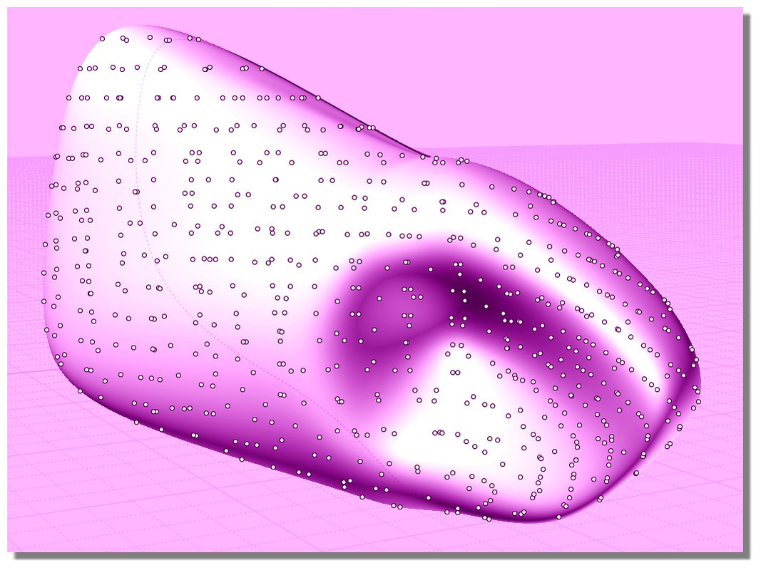
How to do stars faced along local normal? I`ve thought that every point is facing up like normal direction. I know that you are doing flat and flow node at the end but I wanted to try in this way.

I have idea also to use ImageRaster to get scale of grids from image (instead of attractor) on flat plane and then project those scales to other grids becouse there is no ImageRaster node but it`s still foggy idea.
Image Attachments:
STARS.jpg
From: Michael Gibson
Hi Pilou,
> Does it possible to see only "visible points" ?(and not in the same times the points who are behind)
> For a more conprehensive figure! :)
> I can hide them manually but...in case of complex forms that is not so easy to use a selection box! :)
Sorry no there isn't currently a way to do that. The current point display handling is focused on having a small number of points used as strategic markers to refer to. It's not really designed for handling a whole bunch of them like you show there.
- Michael
From: James (JFH)
smdesign,
>> How to do stars faced along local normal? <<
MoI does not AFAIK provide details of surface normals. It is however something that Michael has spoken about being on the roadmap. I did a quick search of the forum and see that it has been on the to-do list for sometime now:
http://moi3d.com/forum/index.php?webtag=MOI&msg=5004.2
.>> I know that you are doing flat and flow node at the end <<
Yes it is easier to use this approach, but of course the flowed objects are distorted which may not be desirable.
However extracting points from a surface using isocrv + pathArray will only give rotational info of points along the iso-curves and hence normal compound curvature info of base surface is lost. However what you want is achievable, albeit via a long and windy route. I have attached .nod file below.

>> use ImageRaster to get scale of grids from image (instead of attractor) <<
This as well has been on my wishlist, and Max has done the foundational work with his RasterImage & Heightmap scripts. The pertinent code segment just* need to be wrapped into a node that has an image import input and a num array output. This numArray output could then be plugged into z input of points for height maps, or into setStyle for colour mapping, or circle radii for halftone screen images etc etc. The possibilities are endless, but we have to wait.
*I say "just", but it is nor within my capabilities.
I know that things are often not as obvious as they probably should be, but generally work-arounds can be found.
Just keep at it
James
https://www.instagram.com/nodeology/Attachments:
starsOnSurface.nod
Image Attachments:
Screen Shot 2019-10-31 at 7.59.gif
From: Michael Gibson
Hi James, the Oct-10-2019 v4 beta has introduced some functions for evaluating surface normals by scripts:
Add script properties to Face objects:
face.domainMin : Property that returns u,v coordinate of the lower left of the surface's parameter range.
face.domainMax : Property that returns u,v coordinate of the upper right of the surface's parameter range.
face.evaluatePoint( uv, u_from_left, v_from_left ) : Function that evaluates a uv parameter value and returns a 3D point.
face.evaluateNormal( uv ) : Function that evaluates a uv parameter value and returns a normal vector.
face.evaluate1stDerivatives( uv, u_from_left, v_from_left ) : Function that evaluates a uv parameter value and returns first derivatives as a list containing [pt, du, dv, duv].
face.evaluate2ndDerivatives( uv, u_from_left, v_from_left ) : Function that evaluates a uv parameter value and returns first and second derivatives as a list containing [pt, du, dv, duv, duu, dvv].
face.isPlanar : Property that returns true if the surface is planar.
face.planarFrame : Property that returns a coordinate from for a planar surface. Only valid if isPlanar returns true.
face.isOnPlane( frame ) : Function that returns true if the surface is planar and is on the given coordinate frame's x/y plane.
face.isOnParallelPlane( frame ) : Function that returns true if the surface is planar and is on a plane parallel to the given coordinate frame's x/y plane.
- Michael
Message 9547.22 was deleted
From: mkdm
Great to know! :)
From: mdesign
@James: Thanks James. Once again. I need to dig into it.
@Michael: Is it changing something with calulation local Normal direction from point layed over the surface? I see that face.evaluateNormal( uv ) and I not`t understand what is U and V values. I know UV but in polygonal modeling.
https://www.researchgate.net/profile/Arthur_Van_Der_Harten/publication/260596792/figure/fig2/AS:296811131621382@1447776696970/NURBS-Surface-parametrized-with-u-and-v-values-from-0-to-1.png
Is it works also for rounded shapes? Is there some node to return U and V values for given point? I yes then it should be easy to get normal direction after your latest update.
From: Michael Gibson
Hi mdesign,
re:
> @Michael: Is it changing something with calulation local Normal direction from point layed over the surface?
> I see that face.evaluateNormal( uv ) and I not`t understand what is U and V values. I know UV but in
> polygonal modeling.
Every NURBS surface has a 2 dimensional UV space associated with it, it's similar to the UV coordinates in polygon modeling.
> Is it works also for rounded shapes?
Yes, it's the same for every NURBS surface. A NURBS surface is made up of a grid of control points going in the U and V directions.
> Is there some node to return U and V values for given point? I yes then it should be easy to get
> normal direction after your latest update.
Sorry no the part of calculating the U and V values that correspond to a 3D point is not set up for script access yet. The "natural" way that NURBS are evaluated is by their parameter space coordinates. Calculating the UV coordinates of a 3D point is not really a part of the natural surface evaluation, it has to be done by a more specialized kind of solver.
- Michael
Show messages:
1-5
6-25
26-45
46-54