Show messages:
1-10
11-27
From: Curious (NEWGUY)
Hi Michael,
>> Those particular curves don't seem to be in your previous model file, can you post them?
They were there, maybe one was missing. Here I attached a new file. In this file I copied and pasted the exact same curves and the resulting lofted geo seems cleaner strangely! I then filleted the top area and it gave creases again but I did undo and retried fillet and it seems to be cleaner? I am using Ver.4 Beta Feb-27-2019.
Attachments:
 TestSend-1C.3dm
Image Attachments:
Q-1C.jpg
From: Curious (NEWGUY)
Hi Pilou,
>> If you rebuild the curve before Loft you will have a very regular curve with a minimum of Control points!
I will keep that in mind.
Do you know script for rebuilding curve so I can shortcut it? Actually I will try to search for list of useful scripts that I can shortcut.
From: Frenchy Pilou (PILOU)
just write rebuild in the right column of the shortcut
or reconstructcurve if you have load it also ! (permit Polylines)
http://kyticka.webzdarma.cz/3d/moi/#ReconstructCurve
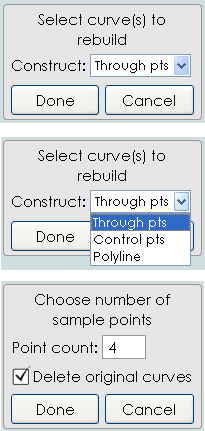
or use ELEPHANT it has in section curve2 / ReconstructCurve & RebuildCurve
Be patient i will make it this evening! :) ( scroll )
http://moiscript.weebly.com/curves2.html#curveblend
From: Michael Gibson
Hi Curious, re:
> Her for example I selected the 2 blue curves and just hit loft, the resulting geometry is super dense!
Even with the new file I can't seem to reproduce this screenshot above, I don't see the upper curve. I've got these ones:

But the one in your screenshot seems to have points here for example which I can't find:

Over here lofting the curves from those files doesn't make a dense surface:

But if they get rebuilt then they seem unusually dense. I don't really see anything wrong with them so I'm not sure why yet, I'll investigate it some more tomorrow after the new v4 beta release. The current v4 beta is going to expire in just a couple of days so I've got to get a new one put out today.
- Michael
Image Attachments:
curious_loft1.jpg
curious_loft2.jpg
curious_loft3.jpg
From: Curious (NEWGUY)
This is the closest I could come to the gold coloured form that I was aiming for :-(
- The area marked "A" should be smooth like in the gold coloured image and not the way I ended up on the purple model lol
- Even the purple model the way it is right now I could not apply variable fillet as I was not able to apply any fillet first like in the YouTube video that was linked by Pilou.
Any help on how to get the gold image detail so one side is completely blended into the side?
Also why the fillet does not work on the purple model?
Attachments:
TestSend-1D.3dm
Image Attachments:
Q2-C.jpg
From: Frenchy Pilou (PILOU)
About the video
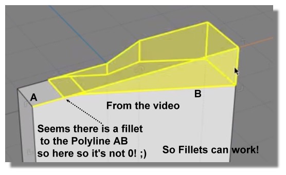
Another strategy if you don't success with the video ;)
I exagerate the shell & Fillet for you can see :)
So you have the fillets of the Front
Kill the faces shelled
recall the Bottom hole
make similar with the bottom if needing
maybe some trim and past
et voila...
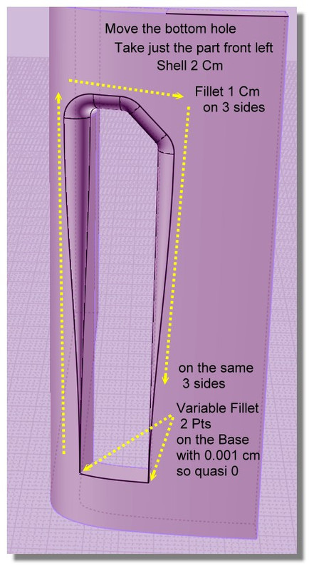
From: moujiik
Hi Curious, In response to Q2, here is the model. I made some project curves, sweep, and shell, all the curves are in the model.
Attachments:
TestSend-1Dre1re2.3dm
Image Attachments:
2019-10-13_001231.png
From: Michael Gibson
Hi Curious,
re:
> Also why the fillet does not work on the purple model?
The thin sharp meeting edges at the bottom with surfaces smooth at the bottom is a difficult fillet case, there is some discussion here:
http://moi3d.com/forum/index.php?webtag=MOI&msg=9512.2
You can use the technique there to get most of the fillets for yours but the skinniest area of yours would need some manual trimming and surfacing to fill in.
- Michael
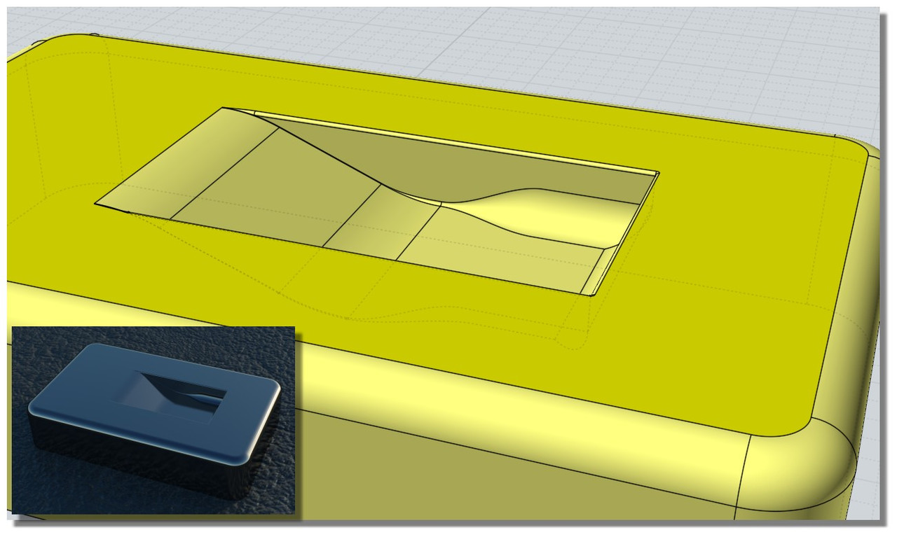
From: Michael Gibson
Hi Curious, so for your gold shape that's pretty difficult. One of the main ways to build a separate piece and have it appear seamless to an existing surface is to have some space between them and use Construct > Blend to make a new surface between them that is smooth to either side. But this becomes difficult if you're trying to make things smooth between 2 different directions at a corner.
To avoid that kind of blend at a corner problem it can work to slice things up so that there is a smooth shape there instead of a corner.
Here's how that would go in your case here.
First you need to get a surface built that touches the sides you're going to want to be smooth but has the curled in part. There are several possible ways that you could approach this, one way that I wanted to try was to model the curl coming off of a plane instead of directly "in place" on your model and then map it onto your main shape using Transform > Deform > Flow with the "projective" option. That looks like this:
I took 2 straight lines from your profile curves, and then drew in 2 curves like this for the sunken corner:

Then Construct > Network to build a curled-corner surface:

Then added a plane surface:

Now Transform > Deform > Flow with the "Projective" option can push the curled surface onto the main shape and it will have the same relation to the main shape as the starting shape has to that base plane surface:

The part that's good about using Flow to generate the surface is it is kind of easier to reason about and to adjust the generating shape that comes off of a flat plane rather than trying to draw them directly in place on a curved surface.
So now the tricky part is that the new surface is not going to be totally smooth at its boundaries to the main shape. It will touch the main shape but not have the same surface curvature where it touches so there will be a slight crease visible between them if you were to just cut out a rectangle hole.
To make things have a smooth connection you can open up some space between them and use Construct > Blend to put in a blend surface. But a blend surface is a 2-sided thing. So to make it possible to put in one blend there between them the space that you open up would need to look something like this:

That's done by trimming the main body with a profile like this:

And trimming the curled in surface with a profile like this:

That then gives this area to put in a blend surface:

This type of Trim & Blend surface modeling is a pretty advanced area of NURBS modeling, it takes a lot more time to learn than stuff like mechanical parts. But it's a method that can work for making some local different shaped feature in the middle of an existing surface.
- Michael
Attachments:
TestSend-1D_flow_and_blend.3dm
Image Attachments:
curious_indent1.jpg
curious_indent2.jpg
curious_indent3.jpg
curious_indent4.jpg
curious_indent5.jpg
curious_indent6.jpg
curious_indent7.jpg
curious_indent8.jpg
From: Michael Gibson
There's also an example here of using this kind of technique for making a local ridge feature in the middle of an existing surface but connecting smoothly to the main surface:
http://moi3d.com/forum/index.php?webtag=MOI&msg=7516.11
- Michael
From: Frenchy Pilou (PILOU)
I have remade the video for be sure! :)
As I said previously the crucial point is minute 0.50...
so no problem! :)
From: Curious (NEWGUY)
Hello and thanks to eyeryone who has replied and kindly speant time and effort helping me!!!!
I came here to post more but saw that there are new posts lol I will read them after I post...thanks.
I have 5 models in the new attached scene in a row, from right to left
1A- Without any fillet
1B- Fillet of .02 on inside and outside. Was not able to apply inside and outside fillet at the same time to do any variable fillet testing. One after the other only. Sometimes it does not even apply at all.
1C- Variable fillet of .02 going to .3 ( Inside only)
1D- Variable fillet of .02 to .3 on the outside (Outside only)
1D might be the most usable as things stand.
*** 2A- Has brand new geometry in the detail region and on this I am not able to apply any kind of fillet at all!!! Could someone please tell me why I can't apply even .02 fillet on the blue model? What is defective on it compared to the green model?
Thank you very much :-)

Attachments:
jeez-1.3dm
Image Attachments:
jeez-1.jpg
From: Frenchy Pilou (PILOU)
Does these 5 models are strictly the same ? (not yet examined)
Ps why do not use the grid and don't float in the free 3D space? :)
Aligned to some axis on the ground for example...
and some times it's also dangerous to be faraway the origine for dark questions of internal decimal calculus...
...and if you don't want see axe, grid, you can hide them in the options! :)
(but please put them on it before :)
From: Curious (NEWGUY)
>> Does these 5 models are strictly the same ? (not yet examined)
The 5th BLUE one is different in that the cut detail area is done new.
Sorry about not aligning it.
From: Michael Gibson
Hi Curious,
> *** 2A- Has brand new geometry in the detail region and on this I am not able to apply any kind of fillet at
> all!!! Could someone please tell me why I can't apply even .02 fillet on the blue model? What is defective
> on it compared to the green model?
Well one problem is it's not very good quality surface geometry especially at the pointy skinny spots which are already difficult things to fillet.
For example this pointy part here:

That is a stressed surface with one side of it collapsed down to a single point. The surface has a structure like this:

The problem with that is that NURBS surfaces are inherently 4-sided things. To get a 3 sided shape it is possible to squash one edge down to a point but it's generally good to avoid that when possible. It's ok when it's the pole of a sphere or a cone or surface of revolution but when you have a shape that is coming from a 2D profile from one direction like you have here the best quality surface is going to be an extrusion that is trimmed.
So good quality geometry for that kind of shape should look like this:

The underlying surface is an extrusion and the pointy areas are formed by areas of the extrude being trimmed or booleaned.
- Michael
Image Attachments:
curious_surface1.jpg
curious_surface2.jpg
curious_surface3.jpg
From: Michael Gibson
Hi Curious,
re:
> *** 2A- Has brand new geometry in the detail region and on this I am not able to apply any kind
> of fillet at all!!! Could someone please tell me why I can't apply even .02 fillet on the blue model?
> What is defective on it compared to the green model?
I've attached a version of this with simplified extrusion geometry like described above and this should have a better chance at being filleted although it's still a difficult case.
But if you select this you should be able to get a fillet although you can see the juncture at the sharp points is a little weird:


- Michael
Attachments:
jeez-1_2_3dm.zip
Image Attachments:
curious_fillet1.jpg
curious_fillet2.jpg
From: Curious (NEWGUY)
Thanks Michael for all your explanations. I might come back with some follow up questions.
Either way you are amazing!!!!! Thank you and the community.
Show messages:
1-10
11-27