Q1- Sometimes when modeling I get creases when filleting. There seems to be enough space around for the fillet to be smooth. Any idea why the creasing occurs? I am using constant distance otherwise the fillet looks lopsided.
Q2- I made few attempts to make the shape and not getting anywhere. Any idea on how I could do it? I have attached the basic file if you want to test it.
Hi Curious, for Q1 notice how the fillet is split up into multiple sections - that center zone is not a piece of a fillet surface it's a patch put in after the filleter has tried to slice out a self intersecting area of the regular fillet.
I'm not entirely sure if it's because of not enough space or if it's because of low surface quality, if you turn on surface control points you can see they are quite dense and it's possible the surface has a kind of micro-ripple type structure in it which confuses the fillet solvers.
I was thinking maybe not be enough space, I took it into Rhino to test a bit there and Rhino's FilletSrf command starts to go crazy with some bunching up at around radius = 120.
Ok, I think I see why the space is even more limited than it initially appears, it's because there is some significant twisting/skewing of the surfaces.
That kind of skew has an impact on surface shaping and general behavior which can be hard to notice visually. You can kind of think of it sort of as if the surface is dragging one side of it behind the other just as it is also going into a bend.
A better surface would look something more like this:
Rather than this:
How was that surface constructed exactly? I see some curves in there which do not look super dense like the surface. But there seem to be some duplicates stacked up on top of each other.
Question 2
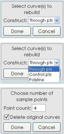
Select Curves
Give same number of points
Press Tab write Rebuild
Use any functions for construct a surface following whished (rounded, flat, etc
et voilà :)
here a simple Loft gives a not rounded one...so sweep 2 rails or any other prodiges :)
Hi Curious, another thing which is probably getting in the way is that your objects are of a fairly large numeric scale and located a fair distance away from the origin.
Some of your strained surfaces are probably the result of some operation in MoI targeting a fitting tolerance of 0.001 units for the calculated result. When your objects are say 8000 units across that's really small in proportion to your object and that's probably why you've ended up with a heavy surface there.
It's better to keep your objects more around say 200 or so units across and positioned near the 0,0,0 origin point instead of a far distance away.
I've been on an ongoing process to try and make fitting tolerances relative to the object size instead of only fixed at 0.001 units to help with this but you're probably running across something that has not been converted to relative tolerances and your object size and position away from the origin are unusual so it's best not to do that. That's probably adding some difficulty to things.
>> How was that surface constructed exactly? I see some curves in there which do not look super dense like the surface. But there seem to be some duplicates stacked up on top of each other.
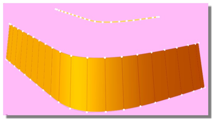
The surface was constructed by lofting those blue non-dense curves. It has actually happened regularly that when lofting simple non dense curves the geometry has become dense. Must be somethign I am doing wrong while lofting etc?
Her for example I selected the 2 blue curves and just hit loft, the resulting geometry is super dense!
> Her for example I selected the 2 blue curves and just hit loft, the resulting geometry is super dense!
So the density in something like that is coming from a rebuild step built into Loft. Those particular curves don't seem to be in your previous model file, can you post them?
Density is not exactly something that has to be avoided at all costs, if it's dense but high quality like no little bumps and ripples that can actually be ok.
> So if I am working on a concept object that is 340cm in length. Should I be modeling it
> in 1/10th scale, so 34cm in length?
I probably would do that, but 340 should generally be ok. But sort of from the way that floating point numbers work each jump in size or even position away from the origin sacrifices some small amount of precision in calculations. That's kind of a separate issue from too tight fitting tolerances though.
<< So if I am working on a concept object that is 340cm in length. Should I be modeling it in 1/10th scale, so 34cm in length?
No just place middle of object at the origine with a raisonnable unity! cm is perfect in this case!
After it's depend of the total size of the project!
<<about Loft
If you rebuild the curve before Loft you will have a very regular curve with a minimum of Control points!
>> Those particular curves don't seem to be in your previous model file, can you post them?
They were there, maybe one was missing. Here I attached a new file. In this file I copied and pasted the exact same curves and the resulting lofted geo seems cleaner strangely! I then filleted the top area and it gave creases again but I did undo and retried fillet and it seems to be cleaner? I am using Ver.4 Beta Feb-27-2019.
>> If you rebuild the curve before Loft you will have a very regular curve with a minimum of Control points!
I will keep that in mind.
Do you know script for rebuilding curve so I can shortcut it? Actually I will try to search for list of useful scripts that I can shortcut.
> Her for example I selected the 2 blue curves and just hit loft, the resulting geometry is super dense!
Even with the new file I can't seem to reproduce this screenshot above, I don't see the upper curve. I've got these ones:
But the one in your screenshot seems to have points here for example which I can't find:
Over here lofting the curves from those files doesn't make a dense surface:
But if they get rebuilt then they seem unusually dense. I don't really see anything wrong with them so I'm not sure why yet, I'll investigate it some more tomorrow after the new v4 beta release. The current v4 beta is going to expire in just a couple of days so I've got to get a new one put out today.
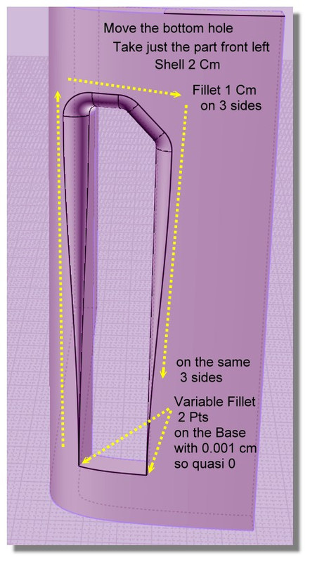
This is the closest I could come to the gold coloured form that I was aiming for :-(
- The area marked "A" should be smooth like in the gold coloured image and not the way I ended up on the purple model lol
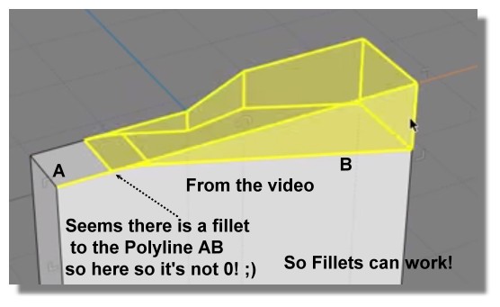
- Even the purple model the way it is right now I could not apply variable fillet as I was not able to apply any fillet first like in the YouTube video that was linked by Pilou.
Any help on how to get the gold image detail so one side is completely blended into the side?
Also why the fillet does not work on the purple model?
You can use the technique there to get most of the fillets for yours but the skinniest area of yours would need some manual trimming and surfacing to fill in.
Hi Curious, so for your gold shape that's pretty difficult. One of the main ways to build a separate piece and have it appear seamless to an existing surface is to have some space between them and use Construct > Blend to make a new surface between them that is smooth to either side. But this becomes difficult if you're trying to make things smooth between 2 different directions at a corner.
To avoid that kind of blend at a corner problem it can work to slice things up so that there is a smooth shape there instead of a corner.
Here's how that would go in your case here.
First you need to get a surface built that touches the sides you're going to want to be smooth but has the curled in part. There are several possible ways that you could approach this, one way that I wanted to try was to model the curl coming off of a plane instead of directly "in place" on your model and then map it onto your main shape using Transform > Deform > Flow with the "projective" option. That looks like this:
I took 2 straight lines from your profile curves, and then drew in 2 curves like this for the sunken corner:
Then Construct > Network to build a curled-corner surface:
Then added a plane surface:
Now Transform > Deform > Flow with the "Projective" option can push the curled surface onto the main shape and it will have the same relation to the main shape as the starting shape has to that base plane surface:
The part that's good about using Flow to generate the surface is it is kind of easier to reason about and to adjust the generating shape that comes off of a flat plane rather than trying to draw them directly in place on a curved surface.
So now the tricky part is that the new surface is not going to be totally smooth at its boundaries to the main shape. It will touch the main shape but not have the same surface curvature where it touches so there will be a slight crease visible between them if you were to just cut out a rectangle hole.
To make things have a smooth connection you can open up some space between them and use Construct > Blend to put in a blend surface. But a blend surface is a 2-sided thing. So to make it possible to put in one blend there between them the space that you open up would need to look something like this:
That's done by trimming the main body with a profile like this:
And trimming the curled in surface with a profile like this:
That then gives this area to put in a blend surface:
This type of Trim & Blend surface modeling is a pretty advanced area of NURBS modeling, it takes a lot more time to learn than stuff like mechanical parts. But it's a method that can work for making some local different shaped feature in the middle of an existing surface.
There's also an example here of using this kind of technique for making a local ridge feature in the middle of an existing surface but connecting smoothly to the main surface: