From: tech
Hi!
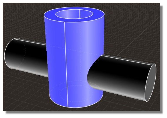
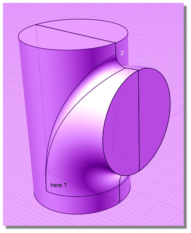
I'm trying to model a special T-shaped module for a pipe system. The problem is that the bool operation fails and I am not able to create the red marked line (in 3 dimensions). Can somebody plz explain to me, how this could be done?
Thanks!

Image Attachments:
 pipe.png
From: Frenchy Pilou (PILOU)
Post your 3dm file!
From: tech
Here it is.
Attachments:
pipe.3dm
From: Frenchy Pilou (PILOU)
Don't yet seen it but in general it's a good habitude to rotate the seams of the objects so the objects!
From: Frenchy Pilou (PILOU)
A cool case for Michael! :)
Ps maybe also don't work in mm but without unity
Message 9499.6 was deleted
From: Stargazer
I gave it a little try. It seems like the boolean fails because the seam lines overlap?
I rotated the cylinder a bit and it worked. I'm not sure if this is what you want.

Another version:

Attachments:
Pipe 2.3dm
Image Attachments:
Image603.jpg
From: Michael Gibson
Hi tech - booleans between objects that have overlapping surface areas or spots that barely graze each other are much more difficult to process cleanly. It's harder for the surface/surface intersector to get a good result in those cases. That's because when surfaces overlap each other they have something more like a "zone of intersection" rather than a crisply defined intersection.
It can help if you have a very tight accuracy on the pieces involved, like in this case instead of using a sweep for the pipe part, use Construct > Revolve. Revolve will make a 100% precise surface of revolution, while sweep will make a fitted surface.
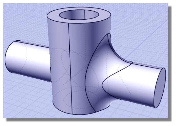
Please try this attached version where I've used Revolve to build the bent piece, it should boolean union ok now.
Another possibility with your original objects is if you cut your objects in half and use ShrinkTrimmedSrf so there are no closed surfaces, that will also avoid some of the other difficult areas of surface/surface intersection. It's then possible to use Construct > Curve > Isect to generate intersection curves and then trim surfaces to those curves.
- Michael
Attachments:
pipe2.3dm
From: Stargazer
Also I wanted to mention that Fillet command does not work on this one. You need to do it manually.
Project some curves onto the pipe and trim the pipes.

Delete the area:

Blend the surfaces:

I'm not sure if there is an easier way. Michael knows the best.
Image Attachments:
Image605.jpg
Image607.jpg
Image608.jpg
From: Frenchy Pilou (PILOU)
...
Ps Funny: an optical effect with the "F" of Fillet who seems not on the same horizontal :)
From: Frenchy Pilou (PILOU)
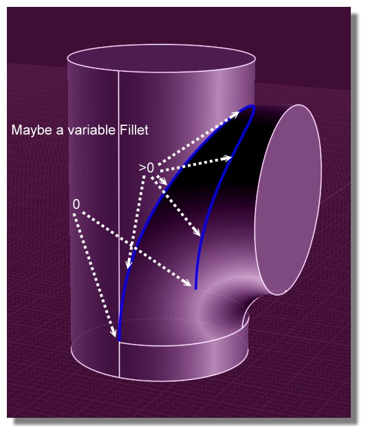
So yes with the variable Fillet we are sure that is zero! :)
Else without this does exist a trick to know the angle of a fillet drawn ?
(here at the base true 0 or not)
when we ask a normal fillet seems a regulate fillet without inflexion like here...but at the base what is the value ?
Variable fillet
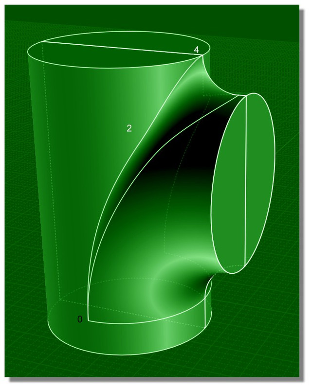
No variable fillet
From: Michael Gibson
Hi Pilou, the regular fillet makes arcs of the same radius value throughout the fillet. But although the arcs are of the same radius, they can have different arc lengths depending on the angle between the surfaces.
When a normal fillet approaches that bottom point, it's not that it is approaching a fillet of 0 radius, it's an arc of your given radius approaching a zero arc width.
- Michael
From: Frenchy Pilou (PILOU)
Thanks for the precisions!
From: Anis
Hi Michael,
I remember you ever have a plan to use this kernel engine to improve filleting:
https://www.kubotek3d.com/products/kosmos
Looks like a few weeks ago they also release new version.
Is there any update on this?
Thank you...
From: Michael Gibson
Hi Anis, sorry I have not heard any news from them as of yet.
- Michael
From: tech
Thank you all for your help!
Rotating the cylinder worked, as well as Michael's revolve solution. But I have a few additional questions:
1) How is it possible to revolve such a 90° arc-pipe ?!?
2) I do not understand the hint with ShrinkTrimmedSrf, how does this help me exactly? (Sorry I don't use MoI very often)
3) Where can I find a variable fillet?
btw I am using V3
Thanks!
From: Frenchy Pilou (PILOU)
1-- Revolve by Rail : Just take the good Axe of Rotation!!! ;)

2 -- Michael will better than me for that! So wait and see! :)
3 -- Variable Fillets : it's inside the Native Fillet Function ! V3 or Beta V4
A very funny one - a little training is necessary
but it's very easy! :)
You can add any number of points, and any number of sets of Fillet! :)
Points are drawn only on a the Current Yellow selection edges after the first General Fillet!
Press "OK" of the numeric Calculate for validate a Radius of Fillet or a Set of Fillet (not Done or Enter)
If you click on the word "current Set" you will see the list of sets for make more editions
Just don't press the final Done (like me here) else you will be "exited" of the function if you want modified something!!!
Here the Radius 2 was yet input from a previous Fillet: Normally you input the general Fillet then the sets of Fillets!
Why you don't load the beta V4 if you have yet the V3 ? Some more powerful and "debugged"! :)
From: Michael Gibson
Hi tech,
re:
> 1) How is it possible to revolve such a 90° arc-pipe ?!?
In the Construct > Revolve command, enter in 90 for the "Angle" option before you pick the revolve axis points:


> 2) I do not understand the hint with ShrinkTrimmedSrf, how does this help me exactly? (Sorry I don't use MoI very often)
Well the way trimmed NURBS surfaces work is there is an "underlying" surface and trim curves are on it that mark cut away areas of it. When you do a boolean or trim operation, the original surface is still there underneath and just new trim curves are generated. When objects are intersected it's these underlying surfaces that are intersected with each other and so if you try to cut away some troublesome part of a surface it's actually still there underneath things. The ShrinkTrimmedSrf command will shrink down excess areas of the underlying surfaces so it's just large enough to hold the trim curves.
> 3) Where can I find a variable fillet?
Like Pilou writes above, it's in the regular Fillet command, you add in a new point set to define a different radius value from the main one at particular points. There's a demo video here:
https://www.youtube.com/watch?v=CemIL-wleOw
- Michael
Image Attachments:
tech_revolve1.jpg
tech_revolve2.jpg
From: tech
Thank you all very much!