Show messages:
1-13
14-33
34-35
From: amur (STEFAN)
Hi Lara,
maybe you can play with a bevel option in C4D to get not such a blobby shape in MoI,
when using the subd2nurbs feature.
 what did deathclaws mutated from
Regards
Stefan
From: amur (STEFAN)
… or for a more CAD look simply use the free Autodesk 123 Design.
Regards
Stefan
From: Lara (MALA)
Thanks a lot for the experiments with my model - and your time!!!
I must sleep over it...
From: OSTexo
Hello,
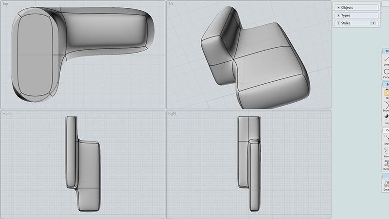
100% modeled in MoI. I do not like the multi blend in MoI as much as in VSR but I think VSR uses a different engine, but hopefully it is an acceptable result in this use case.
I can make a video if you like outlining steps, it's not really too involved, more pre-model planning than anything.

Image Attachments:
 sculpture.png
From: Frenchy Pilou (PILOU)
Sorry what is VSR ?
Yes make a video! :)
From: Lara (MALA)
Video would be cool, please...and thanks...
P.S.: Perhaps you may post your MOI-file?!
From: Lara (MALA)
Hey OSTexo,
what do you mean by "...it´s more pre-model planning"!?
I´m still interested in your workflow...will you find some minutes to make it transparent?!
Cheers, Lara...
From: OSTexo
Hello,
I will be able to upload the video over the next few days.
For this sort of modeling I've found it beneficial to think about model strategy before just jumping into things and trying to cobble something together. It seems like lack of planning tends to have models fall apart.
From: chrisd (CHRIS_DORDONI)
Its an obsolete modeling plugin for Rhino, killed off by Autodesk :)
From: Death
I Made 2 boxes Union-ed them and filleted them, no problem.
Using the latest beta V4
Attachments:
test.3dm
Image Attachments:
test.png
From: jokubart (QOOBAS)
Hi Lara,
Here's my attempt, and my first post on the forums! This was a little more complicated than just a simple fillet. First, I made the fillet curve profile and swept it along the outside of the shapes wherever I could. Then, for the complicated fiddly bit where that didn't work, I intersected two pairs of curves (2nd attached image) to make some complicated rails to sweep that same profile. Once the fillet surfaces were made, I trimmed away the parts of the main shapes that weren't going to be visible. I've attached the 3dm file with the model. Ugh, it's hard to talk about 3d modeling in the abstract, hope this helps!
(PS Michael Gibson, I love working in this program!)
-Jokubart

Attachments:
jokubart_approach.3dm
Image Attachments:
jokubart_approach_1.jpg
jokubart_approach_2.JPG
From: Lara (MALA)
Hi MOIs,
I have completely forgotten to thank you for your attempts: THANK YOU! That's really awesome. I was now able to recreate it well and continue learning.
@Death: Thanks, but I don't think your model is exactly right. One element should not be integrated into the other, but should stand outside it. Like the one from Jokubart a post below.
@Jokubart: Thank you.
One question: It seems trivial, but I can't get it right with my MOI knowledge: How do I move a line without extruding? Otherwise I'll get subdivisions that I want to avoid!
Cheers, ML
From: Michael Gibson
Hi Lara, unlike a polygon modeling you usually don't manipulate NURBS solids by stretching pieces around like that.
It looks like you already have fillets applied to that? It should be ok then to have subdivisions like you're worried about, they shouldn't do any harm.
If you're still stuck, could you please post the .3dm file for your current model so I can take a look?
- Michael
From: Frenchy Pilou (PILOU)
< you usually don't manipulate NURBS solids by stretching pieces around like that.
Better to Add Boolean solid volumes ?
From: Lara (MALA)
Hej Michael, I made a "workaround". This is good for me. Thanks, ML
From: Lara (MALA)
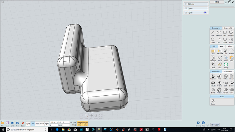
Workaround is not still perfect. (or better...my MOI- skills are not good enough)
1.
There are some lines associated which I intended to delete. But I cant do that. Don´t know what I made wrong!?
2.
The red section is not perfect. But I can´t get it better. And the S-Line for a Loft is in peaces and I´m not able to select it to join for a proper lofting.
Help would be good...
cheers, ML
From: Frenchy Pilou (PILOU)
Your piece is floatting in the space : put in middle of the grid better for eyes tranquility! :)
(and more easy for rotate it! )
Some lines are floating in the Space (object G) Kill it!
Some objects are Hidden ! So Unhide all ! Kill them
Line edges have not same color so surrely belong to some different objects!
Your vertical are not exactly equal between blocks or even in the same block!
200,0000003 against 200,0000000
Some curves are overlapsed
etc...
Seems better efficient to redraw your object...more and more you redraw it more and more you find tricks!
Draw Arc Cont between Lines
Extrude Line for make a surface
3 Quarter Arcs + NetworkWork for make surface
etc...
Select All and press TAB & Write ExplodeMove = you see what is not good! (like lines inside object alone in the space... ;)
etc...
From: Lara (MALA)
uff...a MOI-Pamphlet...too late for that, tomorrow...Thanks Pilou...
From: Michael Gibson
Hi Lara, the line that you can't delete is a squished down surface, those don't behave properly for click selection but you can select it by dragging a selection window around it and then deleting it.
The red piece is a little off from doing a loft between 2 curves of different shapes - when you loft the surface you make will try to connect together at equal distance traveled along each one and since the lower one is longer it's going to kind of shift towards the spiky part of it.
You can get a better idea of this by separating out that piece and using Edit > Show pts to show the surface control points, you can then kind of see how the top and bottom are connecting together from the control points.
Ideally you would get a better surface there by doing a straight extrusion downwards and then trimming it to produce the pointy shape rather than trying to build a surface directly to the pointy shape with one surfacing operation. But I'll have to see if you will be able to get an accurate enough shape to join to the other surfaces with that way.
- Michael
From: Michael Gibson
Hi Lara, please see the attached 3DM version for a replacement for your red surface.
The way I made it was not by directly lofting between that upper and lower edge but instead extruding this one downwards:

So that makes a very regular shaped and extended surface like this:

Then trim it with this to slice the bottom chunk off:

So often with NURBS modeling you don't want to try and build a surface that directly hugs along some irregular shaped boundary, it's often better to build a simplified and extended surface sheet which then gets the irregular boundary applied to it by a trim or boolean cutting operation. That's the main way to get higher quality surfaces, when you trim a surface the surface shape stays the same and it just gets new trimming boundaries on it marking which areas of the surface are active.
Hope that makes sense!
- Michael
Attachments:
ArtForumMOI2.3dm
Image Attachments:
LaraExtrudeTrim1.png
LaraExtrudeTrim2.png
LaraExtrudeTrim3.png
Show messages:
1-13
14-33
34-35