Show messages:
1-17
18-36
From: Frenchy Pilou (PILOU)
I will use one time again the magical function Line-Line (with no scale or other if needing) ;)
With 4 clicks + Helper Lines you can have any positions / Rotations! ;)
and not headaches of the Orient function, CPlane etc... ! :)
If you want insert your cylinder inside the sphere
...the more easy is draw a "Point" on the axe of the cylinder at distance from the base needing
So you can take this point as "markers" for your Line-Line function.
This can be made also by the Helper Lines themselve (Relocate) but..."Point" is more visual! :)

From: Bravlin
The result position of cylinder is a bit different. I need it to be placed not along one of axis.
I need it to be placed along center line that divide sphere on 2 equal parts. And i also need it to be oriented to normal in that position.
But i see how line-line approach can be helpful. Thank you.
By the way line-line have the same snap issues.
Still i'm interested in orient tool & snaps approach.
I guess the main advantage of orient tool is automatic normal alignment.
From: Michael Gibson
Hi Bravlin, it sounds like you're looking for an object snap that would automatically project the y axis onto the sphere. Unfortunately there isn't any built in snap that does that, the only snap that goes on the interior of a surface is either the "on surface" snap from a view direction rayfire, or the "cen" snap on a planar face bounded by line edges like the face of a box. The reason for that is because of performance - there is a lot more computation involved on projection and intersection calculations on surfaces instead of curves. It wouldn't really be a problem on your sphere case but it's also possible to have stuff like a surface with 5,000 x 5,000 control points in it and it would not be good to try and calculate a projection or intersection on a surface like that right in the middle of drawing.
Usually surfaces have a lot more edges to work with and you can target snaps on the edges to get what you need. The sphere happens to be the most sparse type of surface when it comes to edges since it has only a single edge on it.
But you could still make use of that edge if you rotate your sphere into a good position for your pick. You can use the Transform > Rotate command for that or a quick shortcut is to use the "wheel mode" of the edit frame. That's when you click and release on the rotation grip instead of dragging on it. That turns on the rotation wheels and in your case 2 drags would get it to the right position. That looks like this:
So other methods would be that when there is not a built in snap that will automatically give you what you need, you can build some helper curves or points which will have the needed snaps. There are numerous ways you could do this, like draw a line along the y axis and cut the sphere into 2 halves using boolean difference, or draw a y axis line and use Construct > Curve > Project to project it onto the sphere making a great circle on the sphere that you can then snap on to, or draw a line along the z axis that pierces the sphere at your desired spot and use Construct > Curve > Isect to intersect it with the sphere to get a point object to target.
A lot of times some strategic use of construction lines can also get you the needed snap point. In your case here it's possible by making a construction line from the center of the sphere to the end of its edge and reorienting the construction line endpoint to point in your desired direction. The thing that's nice about construction lines is that you can use them when you're in the middle of the orient command and they go away when you're done so you don't need to run any other commands or do any clean up steps. That looks like this:
Let me know if you need more detailed information about any of these methods.
- Michael
From: Frenchy Pilou (PILOU)
<< And i also need it to be oriented to normal in that position.
My method Line-Line works with any Point clicked on the surface of the sphere!
So of course of any curves drawn on this sphere (cutting it in half or any other! :)
Here the curve divides not the Sphere in half, but that will be the same if it's cutting half! ;)
First is clicked on a curve, other anywhere on the sphere!
From: Michael Gibson
Hi Pilou,
re:
> My method Line-Line works with any Point clicked on the surface of the sphere!
Yup, the regular Orient command does as well. But from what I understood it was not just any point on the sphere that was wanted, it was one that was lined up with the world y axis.
The other problem with Line/Line is it can introduce unpredictable rotations if the base line and target line are not all on the same plane. But with a cylinder it doesn't really matter if it rotates around its own axis line.
- Michael
From: Frenchy Pilou (PILOU)
All cylinders axis are crossing on the same shere 's center so good "normal" ! ;)
If not Sphere's center plane needing just take another Helper Line...
<< if the base line and target line are not all on the same plane
Can you show me something like that ?
Seems to me that for the sphere asked that is convenient...
From: Michael Gibson
Hi Pilou,
re:
> Can you show me something like that ?
> Seems to me that for the sphere asked that is convenient...
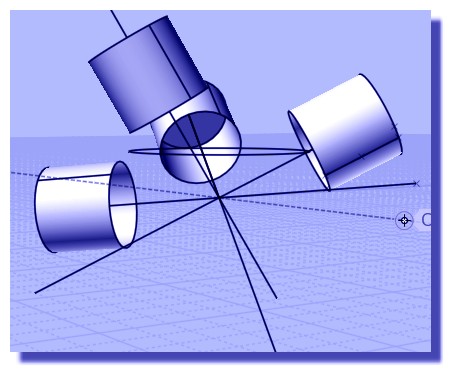
Yes with spheres and cylinders rotation is not really a problem.
On something like this you can see the difference - see how with Line/line there can be a lot of rotation at different positions and you can't really control the rotation, while with the other orient command you can:
- Michael
From: Frenchy Pilou (PILOU)
I can make the same! ;)
Just take the at the base face of the Tobleronne then just follow the perimeter of the box et voilà! ;)
If no same orientation just make 2 Line-line
first : base / Normal (Toblerone) put it somewhere along a Normal of the Face Box
second : base / Edge Base (Toblerone ) like above first video of this post! ;)
Sure it's 2 functions against One Orient but maybe more simple... :)
First: for have same orientation of the base (the 2 bases are now // )
second : then same as first video of this post! ;)
If you want an specific angle of rotation
just type it inside the input numeric entry and over fly over the face's box... ;)
From: Michael Gibson
Hi Pilou, you're still working with special cases there, try this attached 3DM file.
With full orient you can do this:
The line to line orient is primarily intended to be used for 2D operations on curves all on the same plane. It can be used in other situations too but can introduce unwanted pivoting around the lines.
- Michael
Attachments:
 pilou_orient.3dm
From: Frenchy Pilou (PILOU)
It's stricly the same that i show in my post above! ;) (i try of course with your 2 objects)
As I take the normal base face with the Helpers Line ... faces of the 2 objects will be // so i can make the trick of the first video! ;)
I made as i said 2 Line-line...
Object is not aligned when the mouse is not on the face ! ;)
If i want the same result than your i stop the rotation when Helper Lines said 90° (or I type 90°)
I am agree it's 2 functions against one but I have the "scaling" more inside if wanted! ;)
And I am more fluent with the Line-line that the rotation ;)
And it's my favorite function! ;)
From: Michael Gibson
Hi Pilou, maybe you're not looking closely at the result you're getting. Can you post your result?
> As I take the normal base face with the Helpers Line ... faces of the
> 2 objects will be // so i can make the trick of the first video! ;)
Sorry I'm not understanding this part. Could you maybe show the full sequence of what you are doing?
- Michael
Message 9136.29 was deleted
From: Bravlin
Thank you Michael for video answers. Its always easier to see and analyze the process then read about it.
Yes the construction line approach is easiest one but its not universal. That's why i place sphere in that position ;)
Due xsi plugin development experience i always use one final performance test. I tried all my tools on a sphere divided x6.
It's a pretty heavy object. So i totally agree raycast and closest point calculation in a loop or callback may be pretty expensive.
I guess i just expect some kind of cad miracle for that case but it's not always available.
PILOU, the approach in post 9136.21 is handy. But it also need additional manipulation to place it right along Y axis plane.
From: Michael Gibson
Hi Bravlin, you're welcome! And actually one surface snap operation that could work would be a surface intersection with a construction line or line curve. The ray cast calculation doesn't have as difficult performance as something like an automatic curve projection or intersection between a general curve or surface or between 2 surfaces. So one that might be possible to add in the MoI v5 timeframe.
One other thing I wanted to mention was:
re:
> We also can't use ortho views if we want cylinder to be oriented towards normal (i assume that it
> somehow related to raycast mechanisme etc.).
Various surface snapping methods are intentionally disabled in the ortho views. That's because it is easy to draw say something like this in a maximized Top view:

And from how it looks one can easily think that they drew this:

When in fact what was actually drawn was this:

Basically the problem is that it can easily happen that in an ortho view the entire drawing area is filled with "on surface" snaps and so if those did engage it gets in the way of making a 2D shape. So when you are picking points in an ortho view MoI is focused on making 2D results and things like "on surface" snaps do not engage. But they do engage if you pick them in the 3D view - in the 3D view it is harder to get confused about getting a 2D or 3D result and so when you work in the 3D view it gives you the 3D point locations for point picking.
There are various settings in moi.ini that you can alter to modify this though, these are the default values:
[Drawing Aids]
StraightSnapDisableSurfaceNormalInOrtho=y
ProjectOsnapsInOrthoViews=y
DisableOnSrfInOrtho=y
DisableOnSrfInOrthoWhenGridSnap=y
DisableOnSrfWhenGridSnap=n
and for the next v4 beta there will also be
AllowSnapPlaneChangeInOrtho=n
StraightSnapDisableSurfaceNormalInOrtho=y - this one disables the surface normal straight snap in ortho views.
ProjectOsnapsInOrthoViews=y - this makes snapped points after the initial one project onto a plane going through the first picked point, in ortho views only.
DisableOnSrfInOrtho=y - disables "On srf" object snap in ortho views.
DisableOnSrfInOrthoWhenGridSnap=y - disables "On srf" object snap in ortho views but only when a grid snap is targeted.
DisableOnSrfWhenGridSnap=n - disables "On srf" object snap in any view when a grid snap is targeted.
AllowSnapPlaneChangeInOrtho=n - allows the orientation picker to align to surface normals in ortho views. (new in next beta)
So anyway the default concept is basically: Draw in a ortho view tries to give you 2D planar results, while picking points in the 3D view gives you unconstrained 3D and possibly non-planar result. This behavior is a result of seeing people get confused with making non-planar stuff in maximized ortho views where they were expecting to do 2D drawing.
- Michael
Image Attachments:
bravlin_ortho_srf_snap1.jpg
bravlin_ortho_srf_snap2.jpg
bravlin_ortho_srf_snap3.jpg
From: Frenchy Pilou (PILOU)
First sequence for make any faces or objects to be parallal (who have themselves 3 rotations in the space! )
the Line-line + helpers line are sufficient
The 2 objects have now parallal base's faces!
Second sequence for past anywhere Base / base faces' objects
Now the objects will be perpendicular / Base/base with any orientation wanted
(mouse must on the face or parameter of the Base's target object! )
I will send in a moment the result with your object! ;)
http://moiscript.weebly.com/uploads/3/9/3/8/3938813/michael_orient.3dm
Ps the little "cutting square" on the yellow object is not 90° so perspective error can be seems exist! ;)
From: Michael Gibson
Hi Pilou, ok but the point is that you can't do just one use of line/line for those situations. For 3D placement the main orient tool is easier and quicker.
Line/line does work well and efficiently when you use it on 2D shapes all in the same plane which is what it was designed to be used for.
- Michael
From: Frenchy Pilou (PILOU)
Cool ! I was affraid that I miss something...
Yes the classic Orient tool is very good and quicker but a little intimidating with
the 4 different combinaisons of cases to check or not!
And the rotation of the axes themselves is a little tricky! ;)
For my part Line-line seems to me more funny (if possible) and can Scale in the same time!
And the use of the Helper Lines add to the pleasure to use it! :)
And I love to use functions for other things that they are made for! ;)
From: Bravlin
By the way what commands should i use to create key shortcut for "orient tool" and "line-line" tool ?
From: Michael Gibson
Hi Bravlin, there is a list of all command names in the Shortcut Keys section of the help file here:
http://moi3d.com/3.0/docs/moi_command_reference11.htm#shortcutkeys
The particular ones you're looking for are Orient and OrientLinetoLine .
- Michael
Show messages:
1-17
18-36