Show messages:
1-7
8-22
From: Michael Gibson
Hi Pilou,
> Curious : seems I have a perfect surface with a 3 curves / Network ?
If you examine it very closely you'll probably find one pointy area is a little different than the other 2.
If you can post the .3dm model file for it I can take a look to show you.
- Michael
From: Frenchy Pilou (PILOU)
So... :)
http://moiscript.weebly.com/uploads/3/9/3/8/3938813/3curves_network.3dm
From: Michael Gibson
Hi Pilou, try intersecting your result with a plane like this:

If you then move those intersection pieces together you can more easily see there is a difference in shape on one side:

Your result does look good visually though. But that might not be enough for other people's needs.
- Michael
Image Attachments:
 pilou_network1.jpg
pilou_network2.jpg
pilou_network1.jpg
pilou_network2.jpg
From: Frenchy Pilou (PILOU)
Effectively that is an hidden tiny glitch visible on this regrouped curves intersected! :)
But for faraway architecture visualisation maybe not so disturbing ? :)
Of course for precise machining operation that is annoying!
So Network is not the right tool for these triangular things!
From: mrjynx
I have this image may help.

From: john (T5GLK)
hi michael,
thanks for taking the time to look into my problem, i appreciate it. here is the .3dm file. i have tried to fix the curves and give the curves that lead to the center of the vault the same structure as the outside curves, two points at the edges and a controlpoint in the middle to create the curvature while considering the curves tangents to the center of the vault. i doesnt help me to get a vault with a an even center, instead the three parts are slightly bulging to the middle.
regards
john
Attachments:
vault triangular 01.3dm
From: BurrMan
here are mine....

Image Attachments:
canopy_rig.jpg
From: Michael Gibson
Hi john, I think you will need some advanced surfacing tools that MoI does not currently implement to do it in the way you're trying here, meaning by trying to directly generate surfaces to those outline curves. You could try the NetworkSrf or MatchSrf commands in Rhino for that type of surfacing approach. Another way that might be good is to try making a polygonal outline and use Max's sub-d smoothing plug-in.
For the case you posted I'd probably still try to build it as a single larger dome surface and then trim pieces of those out. You mentioned earlier about having some irregular cases that wouldn't work with that, it would probably help if you could post one of those too.
That would go something like this:


- Michael
Image Attachments:
john_vault1.jpg
john_vault2.jpg
john_vault3.jpg
john_vault4.jpg
john_vault5.jpg
From: Frenchy Pilou (PILOU)
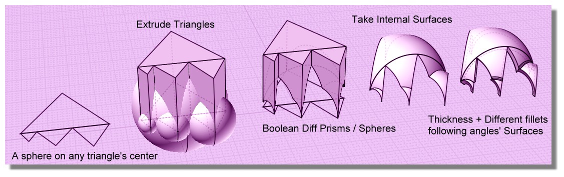
From this method (derivated of the Stefan post) you can have perfect triangular surfaces! :)
Free to you to deform the Sphere on Z before the boolean Diff if you want a more bulged top! :)
(rotate the sphere bottom for not have the generator curve on the top surface! ;)
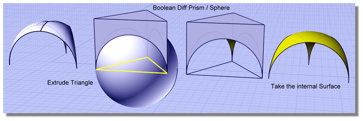
Give a thickness , Boolean Union and you will have any Fillets possible! :)
From: val2
The way I would approach this is make whole spheres into the shapes I want first go through scaling in one direction and showing points on the sphere then stretching the points around to suit. I would have the triangle above the spheres and scale with the spheres. I would then cut with the triangles and then boolean it all together and then remove the bottom. That way you can make all of your decisions while they are sphere shapes and everything after that is just simple labor. if that makes sense.

From: BurrMan
And another.....

Image Attachments:
canopy3.jpg
From: Frenchy Pilou (PILOU)
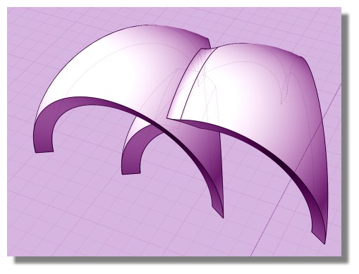
Or like this with different sizes :)
Of course each triangle can be at any Z, spheres can have any Z deformations (or more for crazzy forms) etc...
From: john (T5GLK)
hi michael,
here is the file with a distroted base shape. it is quadrangualar, i think for a triangular base shape it is always possible to find a sphere that touches all the edges. i think the solution from val 2 illustrates that really well, it looks like alle the vaults are fitting together perfectly. maybe next time i ll create a design based on triangular vaults.
i tried to use your approach for the quadrangular distorted base shape and created an irregluar circle and i think it works quite nicely, but the sides of the vault don t match the original curves exactly, similar to your example. it would be difficult to have several vaults next to each other that match perfectly (screenshot distorted vaults 01 and 02). maybe a solution for this problem can be constructed, but my math skills are simply not good enough, which is why i worked around it in c4d with sub division modelling.
thanks again to everyone for posting different solutions to my problem, i didn t expect so much help it is really appreciated!!
kind regards
john


Attachments:
vault quadrangular 01.3dm
Image Attachments:
screenshot distorted vaults 01.JPG
screenshot distorted vaults 02.JPG
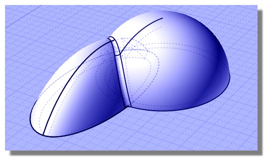
From: Frenchy Pilou (PILOU)
Why not Rail Revolve ?
Height as you want : Arcs by 3 Points
One for the ellipse, one for the circle
then Union, then Thickness then Fillet
Here 2 differents heights
From: Michael Gibson
Hi john, thanks for posting that. Yes I would probably go with subdivision surface modeling for doing that.
For doing it in NURBS it would work better to change how you're specifying the structure, you'd want to set up dome shapes and have the final edges be created by intersections between the domes rather than starting out with those edges and trying to surface those. If you had all 4-sided areas you could do it by surfacing but it will be difficult with 3 sided areas included. Subdivision surfaces are good at dealing with adapting to topology changes like that.
- Michael
Show messages:
1-7
8-22