From: Lestatdelc
I have run into a situation (multiple issues actually) in creating some objects. Using from cross-section lines and sweeping out a shape using rails, then using the offset-shell command I get some distortions and inaccurate surface shapes. Here is a quick video showing the issue:
https://youtu.be/eOF6zyUzLF8
Another issue is the "network" function does not always follow the outline of the frame precisely.
https://youtu.be/aQobMOX4Qx8
Another weird thing, if I create a revolved shape and rotate it, Moi suddenly alters the radius slightly just by rotating it. I noticed this when I created a revolved shape of precisely 14.375 cm in radius (28.75 cm overall) and rotate it 11.25º it suddenly says it is 28.747431 cm x 28.747431 cm.
From: Michael Gibson
Hi Lestatdelc - the way shelling works for an opening is it offsets the other surfaces and tries to extend those offsets until they run into the opening. When the opening is smooth to the surrounding faces that can't happen. So usually the face to be open needs to meet up with the surrounding surfaces in a sharp edge, not a smooth edge like you have there. You should be able to construct the shell in some manual steps though starting with an offset of your main surface. If you can please post the 3dm model file it would help me give better advice.
> Another issue is the "network" function does not always follow the outline of the frame precisely.
Can you please post the .3dm file and I"ll take a look. Network goes through a fitting process though and it's normal for such things to be off of exact by about 0.001 units. It looks like you're zooming in quite a ways there so you're probably seeing that small deviation.
If you want to have a surface that matches input curves exactly you can't use Network for that, you can get that with some other surfacing commands that do not use any fitting process though like Extrude or Revolve.
> Another weird thing, if I create a revolved shape and rotate it, Moi suddenly alters the radius slightly just by rotating it.
> I noticed this when I created a revolved shape of precisely 14.375 cm in radius (28.75 cm overall) and rotate it 11.25º
> it suddenly says it is 28.747431 cm x 28.747431 cm.
The reported size is the world aligned bounding box size. It's normal for the world aligned bounding box to change in size when objects are rotated.
- Michael
From: Lestatdelc
Here is the .3dm file.
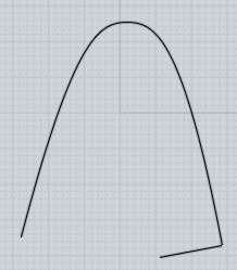
As shown in the video clip, I swept the initial shape using the angled vertices using the upper and lower closed loop rails (the bottom one dropping in the z axis in a subtle curve).
The upper loop "opening" is the where the problems are.
After creating the outer shape, I used "planer" to close the opening using the edge formed by the swept shape. So in theory I would think/assume that the now closed "opening" would be seamlessly filled with the planer created face.
I then "joined" the outer shape with the filled planer face of the "opening" to make a single object.
Shelling (or even offsetting) that object by a sizable amount those anomalous gaps or openings are introduced in what should (at least the assumption at any rate) a fully filled center face.
Attachments:
 bridge-superstructure-WIP-01.3dm
From: Michael Gibson
Hi Lestatdelc, you might try offsetting just the Network surface all by itself - don't join the planar top to it because that makes for a much more difficult offset calculation. It's more difficult because the surface that Network generates won't be totally smooth to the planar top at all areas. It will be smooth at the curve stations but not in between those areas. Offset surfaces will only naturally touch each other if the surfaces being offset are smooth to each other. If not smooth they have to be extended and intersected and that can be difficult when they are close to being smooth but not quite, that makes for a shallow intersection.
Also you might try using Sweep instead of Network for this case - the way sweep works keeps more rigidity to the profile shapes as they travel along the rails, see the attached version generated with sweep which can be offset ok I think. Network is more of a fully bidirectional thing and will be a little more like a soap bubble kind of very slightly flattening out in areas away from the input curves.
I also took a look at the issue you showed with the inexact Network result - the actual distance in the area I zoomed into is 0.000008 units, so it's a very small difference and well below the 0.001 fitting tolerance level. It's normal for many types of generated geometry to have that small level of deviation in them from the original inputs. Many operations use an iterative refinement type mechanism for generating shapes and refine the results until they are within a tight enough tolerance of the original. So that's a normal and expected type of result.
I'm not quite sure of the final shape you're trying to get here, maybe if you described a bit more about how you want your final result formed (like is there an opening at the top or not) I might be able to give some more advice.
- Michael
Attachments:
bridge-superstructure-sweep.3dm
From: Lestatdelc
Thanks Michael. However the issue shown in the video with regards to the shelling/offsetting gaps being introduced were created with "sweep" not "network". The file you attached (which I assume was also created with "sweep") produces the same issue when "shelled" with a large amount (such as a 10 cm shell "normal"). The final shape I am trying to recreate is the upper bridge superstructure of the studio scale filming miniature of the U.S.S. Enterprise from Star Trek: The Motion Picture.
From: Michael Gibson
Hi Lestatdelc - it's not generally feasible to generate an offset or shell with a distance value that is greater than the radius of the bends in your surface shape.
Doing so produces a situation like this where the generated surface will get all bunched up and fold back over top of itself:
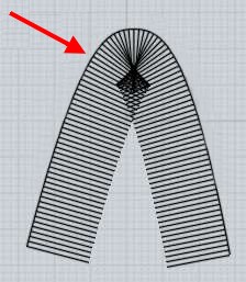
The other thing that can be problematic about a large offset distance in proportion to the base surface is that a surface offset is kind of like taking a stick and running it along the surface normal. With a long "stick" (offset distance) any even very slightly bumpy areas will get magnified at the other end of the stick and not produce a good result.
So it's not going to work to do a shell or offset in the direction that you're trying. If you open the .3dm file I posted previously it is possible to use Offset on that of 10cm in the opposite direction from what you're trying to do. That direction won't get bunched up like the other direction will.
But you'll probably need to model the shape you want out of a new set of curves rather than using shell or offset to do it.
- Michael