From: bemfarmer
SVG export from MoI, to Vectric Aspire:
This purpose of these notes is to document, by example, how the data on an aluminum Plate designed in MoI CAD program, may be transfered by SVG file(s), to Vectric Aspire CAD program, in order to produce gcode for CNC machining of said Plate, out of aluminum Stock material.
MoI is used to design the Plate size and perimeter, as well as the location of holes, countersinks, pockets, etc.
Also, the Stock material may be shown in MoI, and its desired position relative to the Plate determined.
The datum on this relative position should be recorded.
The dimensions of the Stock are 470mm X 146.5mm X 10mm +/-.
The salvaged Stock has the constraints of a few holes to mostly avoid, if possible.
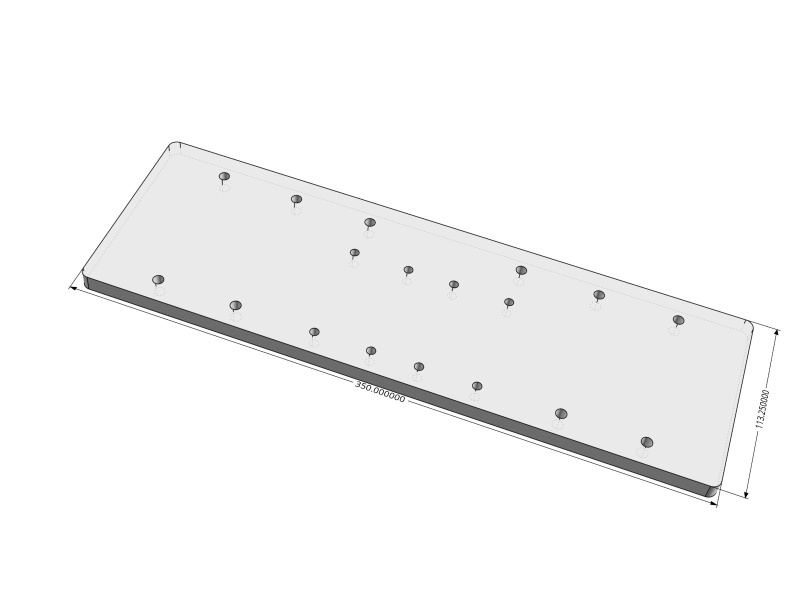
The dimensions determined for the Plate are 350mm X 113.25mm X 10mm.
The design of the Plate was completed in MoI. For this simple Plate, 2 dimensional curves in one plane are sufficient to transfer to Aspire as vectors, in order to create the tool paths needed. If there were additional features to machine in the other surfaces of an extruded solid Plate, additional vectors from these other planes could also be transferred to Aspire. The following pertains to using vectors from the top surface of the Plate.
The SVG export from MoI can utilize the top surface, or just the perimeter and the circles denoting the holes in the Plate. There are multiple permutations of SVG save methods, for different portions of the geometry of the Plate.
Geometry edges of the Plate can be Merged in MoI, or Joined in Aspire, or may sometimes be transferred as joined.
SVG Export does not work for edges or faces of the Extruded Plate.
If the top surface of the Plate is all alone, (not a Face), the SVG Export of the top surface worked well. Vectors (curves) were not duplicated. Vectors were closed.
It might be helpful to have a MoI Script to select a Face of a 10mm thick Plate, which would convert the Face in to a isolated Surface, to which SVG Export is applied.
An alternative would be a Script which converted Edges to Curves, and then applied SVG Export.
The shortcut script Select edges v1.2 already exists.
There is also the script Convert Face to Curves.
SVG Save of the entirely selected extruded Plate caused the duplication of vectors, because the bottom face also has edges. Some perimeter vectors were not closed.
Also SVG Save saved everything, not just a selectable portion of the geometry.
A note on "datum points":
Definition of "datum point" (plural datum points) A point which serves as a reference or base for the measurement of other quantities. (Wikipedia)
The use of imperial units, inches or fractions of inches, is avoided as much as possible, in favor of millimeters, except that the end mill will be 1/8 inches. A Stanley tape measure with dual metric/feet-inches is helpful, as well as a caliper.
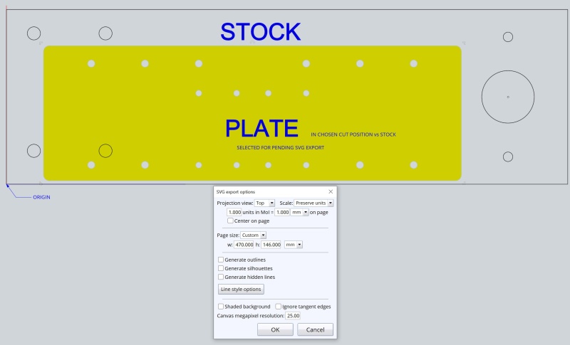
The SVG "paper space" may be considered to be representative of the Stock material. (See SVG export window.)
The SVG Export menu permits the dimensions of the "paper space" to be manually entered, so that the
dimensions of the Stock material may be entered there.
Vectric Aspire will automatically create the paper space Stock material in its View window.
Placement for Lower Left Datum Point will be at the Aspire Origin.
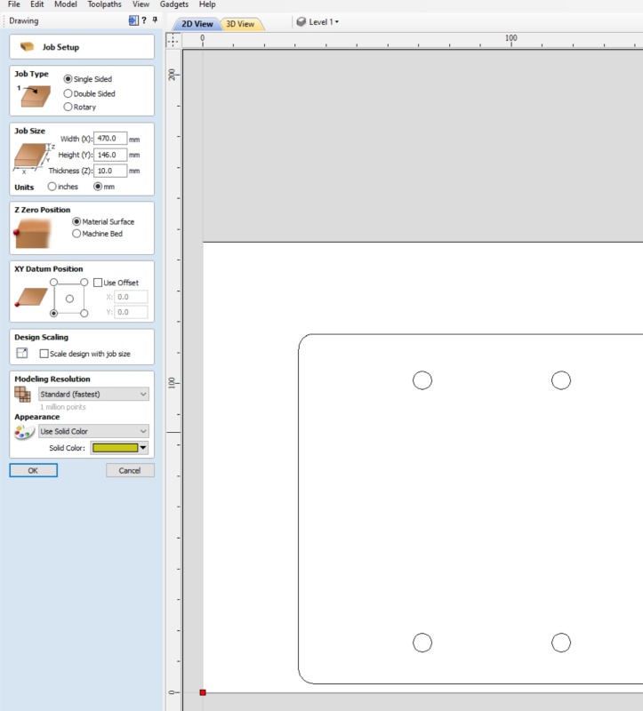
IMPORTANT IMHO: Vectric Aspire Datum initialization:
Before opening an SVG file in Vectric Aspire, it is necessary that the Lower Left Datum point be initiallized. This can easily be done by Aspire> File New, or Create a new file, and selecting said Datum point.
(See the Aspire menu below.) Once initiallized, this setting is persistent, and the created blank material can be deleted. OTHERWISE, the SVG Plate will be entered to a Weird position in the Aspire work space. With this initiallization, the Plate is placed with respect to the Paper Space, corresponding to the position in MoI. Aspire places the paper space with Lower Left corner at the origin. Also it is advisable to set Dimensions in millimeters. After the SVG import occurs, the Aspire Datum Point can be changed, and X,Y ofset, if desired. (I assume that the potential Weird placement of the SVG Plate for incorrect initial Datum Point, is NOT an SVG bug. (?)
Aspire 10.516 was used for testing. Aspire 9.519 was briefly used. On the home computer, Aspire somehow Lost its material and Tool database. This was fixed by re-install.
The Weird Datum Point problem took a long time to figure out.
The creation of Tool Paths in Vectric Aspire is a whole new learning curve. Also Aspire can convert the Tool Paths to gCode for the CNC, once the appropriate Post Processor is installed. The Post Processor database is in a Vectric subdirectory, and the appropriate one needs to be copied to the neighboring folder. The blank Stock material must be placed in the CNC, and the Same relative Datum Point be set in the CNC control software. The Center of material is also sometimes used as a Datum Point. Scrap can be cut to double check the dimensions...
The Yellow Plate shown below is just the separate top Surface, NOT the top face of the extruded Plate.
- Brian
AluminumPlate: