Show messages:
1-7
8-27
28-29
From: Phiro
Hi,
I think, the solution is to use both possibilities of rigidity of flowing.
The sin of your hose could be flowed with a "none rigid flow" (it will be compressed and stretched) and the rings could be flowed with the rigid option (no compression or stretching) to keep their original aspect.
I test it with a boolean unioned sin to have a single solid without hole .
It works !
A problem could appear if you have a too big curvature in path because rings could can clump together because the physical constraints are not possible to be applied.
Message 10840.9 was deleted
From: krass
http://moi3d.com/forum/index.php?webtag=MOI&msg=4722.1
From: Robert (ROBERT_S)
Wow guys you are all amazing each of you.
Thank you all for that help and quick response, really appreciate it.
Love that great community here.
Cheers.
Robert.
From: Robert (ROBERT_S)
Hello guys,
I tried the methods that you posted here, but i can not figure out how to get the result that i want.:/
Can anyone explain step by step what i must to do exactly?
Apologize me guys im new in MOI.
Thank you for your time.
Robert.
From: bemfarmer
Hi Robert,
A rough initial outline:
First determine your target curve.
Unwrap target curve to get base curve, using Michaels UnwrapCurve shortcut script.
The result is a straight line base curve, and is the same length as the target curve.
Determine the profile, (or the two profiles) of a unit of the tubing.
Portion 1 is the cylinder section.
Portion 2 is the "cord" torus section. (Or half torus.)
Array portion 1 and portion 2 along the entire length of the base curve.
(Might have to adjust some lengths, or cut off a little cylinder from the finished hose? Just make sure the length of the base curve equals the length of the target curve.
Portion 1 can be a solid hollow tube, with wall thickness.
Portion 2 could be a solid torus, or a solid half torus, or a shell of a half torus...(?) And be a hollow tube.
Run Flow.
By Phiro's method, which I particularly liked, the cylinder might extend the length of the base curve.
The "cord" torus, or half torus, provides strength and support, and anti-kink features, like the wire spiral helix in an exhaust duct.
First flow the cylinder, settings: regular (nonRigid).
Then flow the many cord tori, setting: rigid.
Boolean or some such...
- Brian
From: bemfarmer
For a vinyl duct hose, the cylinder folds.
For an elastic air hose, part can stretch, and part can shrink, or...
Perhaps the cord half tori should stretch and shrink also.
I wonder if Michael could add a slider, to do a partial percent rigid flow, and partial regular flow?
Somehow multiply the curvature and torsion by a percentage, in the "mapping" algorithm?
- Brian
From: Michael Gibson
Hi Robert,
re:
> I tried the methods that you posted here, but i can not figure out how to get the result that i want.:/
I think you may need to explain a little more about what type of result you want.
So far you've explained that you don't want gaps, so I thought you wanted the pieces to deform to fill in that gap space.
But then you explained that you don't want deformation.
So I know some of the things that you don't want but I don't know much about what you do want.
Do you want the gaps to be filled by some kind of central tube surface? Or something else? What is it that you want to have where you currently have the gaps?
Can you post the model files for some of the things you tried? That might help to give some tips on what was going wrong there.
- Michael
From: Michael Gibson
@Brian,
re:
> I wonder if Michael could add a slider, to do a partial percent rigid flow, and partial regular flow?
> Somehow multiply the curvature and torsion by a percentage, in the "mapping" algorithm?
The "rigid" option for flow transforms just a single centroid point and then moves and rotates the object without deforming it, while the regular deformation method deforms all space.
These are different enough that I don't see how it could work to do a slider with a partial result between them, sorry.
- Michael
From: bemfarmer
Michael, thank you for responding.
I'll do some more google searching, and start a new thread if find anything relevant :-)
Maybe deform space half as much somehow? Scaling target curve? 2D, 3D...
- Brian
From: Michael Gibson
Hi Brian,
re:
> Maybe deform space half as much somehow? Scaling target curve? 2D, 3D...
I don't see how any of those would be possible.
- Michael
From: Robert (ROBERT_S)
Hello Michael,
I'm sorry if my explanation confused you.
I just want make the hose as on the image, without that deformation that happen when i follow the curve.
Here is video of my process:
https://www.youtube.com/watch?v=PhpuPDRsMrM
Maybe someone can tell me, what im doing wrong and how to avoid the deformation.
From: Michael Gibson
Hi Robert, you can avoid the deformation if you use the "Rigid" option in Flow. It's a checkbox that appears in the command options area in the upper right area of the main window when you are running the Flow command.
But if you want to have no deformation it may be better to use Array along curve and initially only create the large rib piece and not the smaller pieces that were inset in your video. So something like this:


Then instead of creating the smaller radius pieces directly on the rib, instead make a tube. To do that draw in a circle at the base of the same path curve, then select the circle and run Construct > Sweep to build a sweep surface:


Having that continuous longer tube be used instead of little nubs on each individual piece will not have any gaps:

If your goal is to render this, you can just be done here, there isn't really any need to boolean the pieces together.
Hope this helps,
- Michael
Image Attachments:
 robert_hose1.jpg
robert_hose2.jpg
robert_hose3.jpg
robert_hose4.jpg
robert_hose5.jpg
robert_hose1.jpg
robert_hose2.jpg
robert_hose3.jpg
robert_hose4.jpg
robert_hose5.jpg
From: Robert (ROBERT_S)
Hey Michael,
This is exactly what i need.
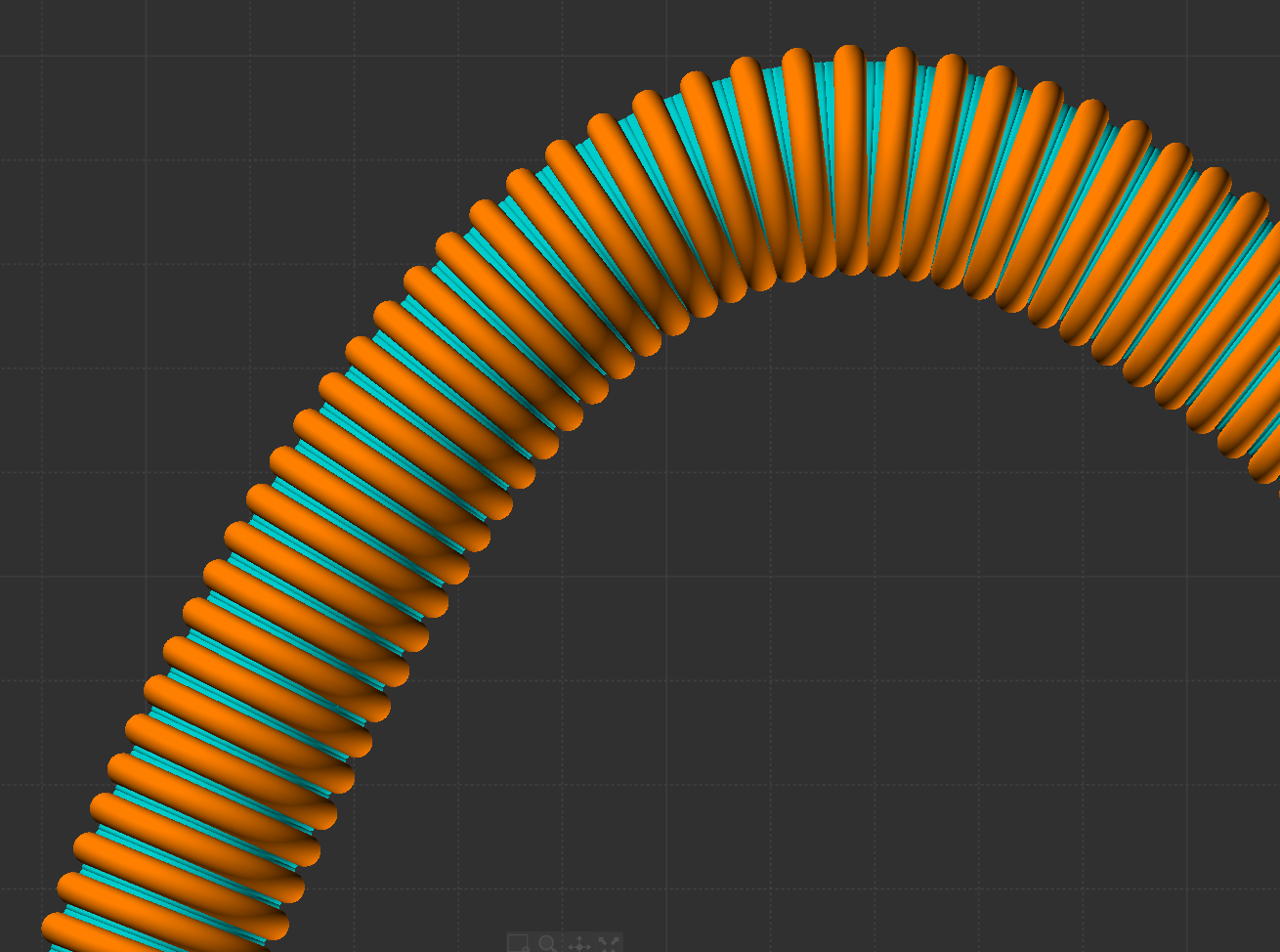
I tried it, but if i follow the object with Array - Curve then it follow like this, why is this happening and is not following the curve as on your image?
What are im doing wrong?
Thanks.
Robert.

Image Attachments:
hose_4.jpg
From: Michael Gibson
Hi Robert, it looks like you need to rotate your starting object so it is oriented perpendicular to the curve's starting direction.
Your object is oriented in this direction:

But that is not aligned with how your curve is formed, you need to rotate your object so it is in this type of direction before arraying it:

The difference from my example is that the one I showed had the curve start direction going along the z axis direction same as the object's normal:

If you're still stuck please post your .3dm file so I can show you how you need to rotate your object.
- Michael
Image Attachments:
robert_array1.jpg
robert_array2.jpg
robert_array3.jpg
From: Robert (ROBERT_S)
Hey Michael,
I tried rotate the object but still nothing.
I feel absolutely dumb right now.
I need to see it how to do it. What im exactly do wrong, other way i will never understand it.
Robert.
Attachments:
HOSE_2.3dm
From: bemfarmer
Hi Robert,
The object is at quite an angle. So I found it a little challenging.
First place a small (green) line along the normal of the object, at the center of a circle portion.
The start of the green line should be at the place in the object where the curve will eventually start, probably the
"left" side of the object, center of circle, with green line, (reverse normal), going to the right.
Also place a lightBlue tangent line at the start of your target curve, from "left" to "right". (reverse tangent.)
Orient Line Line the object with the green and the lightBlue lines.
- Brian
(Or better yet, un-reverse both the normal and the tangent :-)
There are snaps for the Normal and the Tangent. These snaps work in either "direction", 180 degrees...
There is more than one way to do the alignment...
With both the object and the curve at such angles, cPlane would not work, unless...
It might be easier to cPlane the object, with normal along z direction, and save it to a file alone, erase object from curve .3dm.
Then cPlane the curve alone, in z direction, and reload the object in say TopView...
Your curve seems to have a "sharp", rounded, almost 90 degree bend... (unnatural physics?)
A catenary section, or larger arc radius, might seem more natural?
From: Phiro
Hi,
Because a video is more easy to explain the worflow...
Using Orient/orient function
From center of ring to start of curve.
Then Array/Curve function

From: mjs (MSHIDELER)
You could also run a straight line out from the end of the path that you wish to use that is also tangent to your path. Then create your object to array along the path based on the straight line segment. Then trim away the extra section if you don't want any straight parts of the final model
From: Frenchy Pilou (PILOU)
Your problem is the curvature of the curve!
Turns must some rounded!
Seems Flow function is some easy! :)
Show messages:
1-7
8-27
28-29