Show messages:
1-20
21-40
41-60
61-80
81-100
101-120
121-140
141-158
From: Mik (MIKULAS)
Hi Michael,
very good FREE sw for dimensioning is Solid Edge 2D Drafting
https://www.plm.automation.siemens.com/plmapp/education/solid-edge/en_us/free-software/free-2d-cad
and together with Make2D4Views script is effective combo for technical drawing.
... of course this is a special tool for technical drawing, but it could be good source of inspiration for MOI DIM tools.
re:
>Nothing really specific yet, just that I'd like to make it possible to generate a drawing like you show there (not the detail view one though) all in one single export.
IMHO it would be more than enough at the moment.
It would be nice to have command under fold DIM, which generate .3DM file with all set of views in one file, where the 3D models are perpenicularly arranged in TOP view for example, i.e. in opened model I highlight one part, which has to be manufactured = technical drawing, then I click to command and save it to desired place. TOP view appear after opening the file, where it will be seen 4 models in basic views, then I can import and scale the Table, see enclosed, and start create Technical drawing.
I think that 3D models are more advantageous instead of "Make2D curves", because PDF export offers at now many settings for presentation and if I need 2D curves, then I only highlight all models and run Make2D script, resulted curves can be export in DXF, for example.
Mik
Attachments:
 Technical Table sample.3dm
From: Mik (MIKULAS)
Hi Brian,
here
https://www.pdfdrive.com/technical-drawing-books.html is quite good source of Technical drawing books.
Mik
From: Michael Gibson
Hi Mik, so you mean making copies of the object and having them rotated and placed within your title block in the Top view? I guess the thing that would be missing from that would be having perspective for the 3D view.
I was thinking something more like in the PDF export dialog there would be a setting for doing 4 views, and also an option for a title block template which could be a separate 3DM file that you had prepared which would get merged into the PDF output. Maybe there's a named rectangle in the title block template file and the exporter fills in that area with that view.
That could be pretty simple to set up.
Maybe the other piece needed would be a property on dimensions to say whether they display in all views, ortho views only, or 3D view only... ?
I guess it could be for exporting to DXF format as well.
I'd kind of like to make it more oriented towards generating it all in one export instead of a Make2D-like generating it in a sort of "staging area", although Make2D could get the same behavior as well.
- Michael
From: Frenchy Pilou (PILOU)
<< What is it that you are trying to do by having the dimensions separated?
Just to have total absolute complet control of anything! Number, Text, Arrows (part of them) etc...
Move, size, rotate, deformation (Flow) etc...more for design use than technical use...
(i can make yet all that with the Max Smirnov Dimensions but... ;)
Here just Move / Rotation the dimensions itselve for example

PS Your trick of Export / Import works also but some regulates must be done during the process! ;)
(unities, view...)
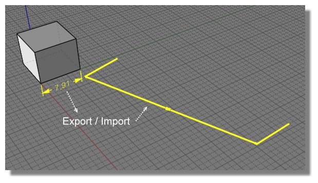
PS Seems there is something wrong somewhere : I don't success to re import in the same Size / View / Position
else dimensions, arrows and lines themselves are good! (except of course surfaces as you said above:)
https://moiscript.weebly.com/uploads/3/9/3/8/3938813/not_same.3dm
From: fcwilt
Hi,
Sorry my bad.
The taskbar shortcut I was using was still invoking the previous beta release.
The current release no longer marks the file as changed on export of STL.
Thanks for fixing that.
Frederick
From: Mik (MIKULAS)
Hi Michael,
concept which I mean is based on Make2D4Views script, which generate 4 views (according viewports views I have set) like most technical drawings, pls see here
https://i.stack.imgur.com/xwJwc.jpg or here
https://en.wikipedia.org/wiki/Engineering_drawing#Line_styles_and_types
This script is perfect, but doesn't offer so many PDF export settings, like in case of solid/surface model, where I can change line styles, hidden lines are automaticly in dashed line style, shaded backround makes drawing more cool if it's necessary.
Therefore I copied and rotated model manually to achieve same arrangement like in case of Make2D4Views script, pls see enclosed.
Re:
>I was thinking something more like in the PDF export dialog there would be a setting for doing 4 views, and also an option for a title block template which could be a separate 3DM file that you had prepared which would get merged into the PDF output. Maybe there's a named rectangle in the title block template file and the exporter fills in that area with that view.
It would be great! Do you mean that final 3DM will contain merged objects in 4 views + block template and then we can start with dimensionsioning or exporter will generate PDF with 4 views + block template, then we import PDF into MOI and start dimensionsioning?
Re:
>Maybe the other piece needed would be a property on dimensions to say whether they display in all views, ortho views only, or 3D view only... ?
Yes, it woud be fine.
Mik
Attachments:
Dim Test.zip
From: Michael Gibson
Hi Pilou, for moving the text you can do that with a regular dimension by selecting it and turning on edit points using Edit > Show pts. There will be a point on the text which you can drag to reposition it. The dimension text will also automatically rotate itself to be legible in any view of it so you don't need to manually rotate it.
> PS Seems there is something wrong somewhere : I don't success to re import in the same Size / View / Position
> else dimensions, arrows and lines themselves are good! (except of course surfaces as you said above:)
Well the PDF/AI file only has 2D coordinates so when you read it back in it's going to be on the x/y "Top" plane.
For your case there you could do it like this:
Select dimension, export to PDF format using "Projection view: Right", "Scale: Preserve units", 1 units in MoI = 1 cm on page, and "Center on page" off.
Next run File > Import, pick your PDF file, then run Transform > Orient > View to view and click once in the Top view and then next in the Right view to reposition the dim back to the Front view.
- Michael
From: Frenchy Pilou (PILOU)
<< for moving the text...
yes but the " text number " stays at the same place between arrows (who move too) !
It's not free itself till i Export / Import PDF ;)
<< Export / Import PDF - AI
Tricky & a little cerebral but Excellent!!!
THX for all!
From: Michael Gibson
Hi Pilou,
re:
> yes but the " text number " stays at the same place between arrows (who move too) !
> It's not free itself till i Export / Import PDF ;)
That will happen if you drag the points at the ends of the arrow line.
If you drag the point that is on the text you can move the text freely independent from the arrow line, here is an example:
- Michael
From: Frenchy Pilou (PILOU)
Indeed! Very cool! I have picked the bad point! 1/3 :)
Else for the other one Export / Import (i have artificially lower position original for better see )
all works fine except
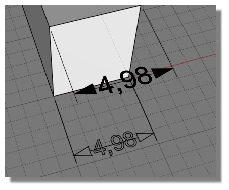
a little problem of text size... i have followed your info above but...(a bug or a bad options from my part?)
seems very small against the original! All was made in the same session!
I have Cm as Unities system enabled before draw something
not visible here because I have not add it after the <> in the Details' box
From: Michael Gibson
Hi Pilou, yes for text size to be preserved in this case you would need to set the option for "Scaling: By model units" on the dimension's properties.
- Michael
From: Michael Gibson
Hi Mik,
re:
> It would be great! Do you mean that final 3DM will contain merged objects in 4 views + block
> template and then we can start with dimensionsioning or exporter will generate PDF with 4
> views + block template, then we import PDF into MOI and start dimensionsioning?
So I mean more like this - you have your model you've made in one file, and a title block template set up in a separate file. Now go ahead and add in dimensions on your model. Then you export to PDF and there is an option for the view configuration. It would have options for "Top", "Front", "Right", "3D" (all single view drawings as it is now), "4 views", or "Use title block template".
If you set "Use title block template", it would compose the PDF by pulling in your title block template file and looking through it for any rectangles that have been given an object name of "Top", "Front", "Right", or "3D" and when it finds those it will generate that view and put it inside there.
- Michael
From: Frenchy Pilou (PILOU)
Ok this time all works fine! And all is editable! ;)
From: pafurijaz
Great update, I love it now the overlapping vertex with imported obj for subDiv don't make crashes..
From: Larry Fahnoe (FAHNOE)
Hi Michael,
> So I mean more like this - you have your model you've made in one file, and a title block
> template set up in a separate file. Now go ahead and add in dimensions on your model.
> Then you export to PDF and there is an option for the view configuration. It would have
> options for "Top", "Front", "Right", "3D" (all single view drawings as it is now), "4 views",
> or "Use title block template".
> If you set "Use title block template", it would compose the PDF by pulling in your title block
> template file and looking through it for any rectangles that have been given an object name
> of "Top", "Front", "Right", or "3D" and when it finds those it will generate that view and put
> it inside there.
This will be a wonderful feature addition! As Santa Claus, you're making a lot of work for yourself & like ungrateful children, the present (v4) is barely opened and we're already looking forward to the next one (v5)!!! ;-}
--Larry
From: Larry Fahnoe (FAHNOE)
I was playing with dimensions and encountered a problem dimensioning the radius of the edge of a solid.
Steps I took:
1) Draw solid box
2) Draw solid sphere overlapping box
3) Boolean Diff, with sphere as cutting object
4) DimRadius one of the arc edges that the sphere cut
DimRadius command runs but doesn't display an arrow or center point. Clicking on Arrow location and Text location doesn't produce a radius dimension.
Thinking it was due to this being an edge, I selected the edge and copy/paste to create a curve and then tried DimRadius the curve, same results. Am I doing something wrong, or have I stumbled upon a bug? Model attached.
--Larry
Attachments:
Arc dim problem.3dm
From: bemfarmer
I would say that neither the edge curve, nor the curve from copying the edge curve, are being recognized as a circular arc.
A new arc draw over top of the edge is recognized as a curcular arc, and the dim arc works fine.
Cannot remember all of the new curve methods...is a line, is an arc (?), is open, is closed, etc... to see how the curve is ID'd.
How does MoI know if a curve is an arc?
- Brian
From: nameless
Hey Michael, thank you for the awesome additions! Also, congrats on a squeaky-clean to-do list! This must be a rare state for you :))
moi.ui.getLastOrientationPickerFrame() <- Is this what I think it is? *rubs eyes with excitement*
Can't wait to try this version out. Much love!
From: Larry Fahnoe (FAHNOE)
Hi Brian,
Indeed, neither the edge nor curve that resulted from copy/paste of the edge are arcs:
The edge's Details are: Open edge, Joined, Planar
The pasted curve's details are: Open curve, Planar, 1 segment
And a real arc's details are: Open curve,
Arc, Planar, 1 segment
From the API perspective I believe the relevant properties are isCircle and isArc.
Odd though that a boolean diff with a sphere as cutting object wouldn't have left an arc behind but I suppose it depends upon the object being cut.
> How does MoI know if a curve is an arc?
It's Halloween, so it must just be magic... ;-}
--Larry
From: bemfarmer
:-)
Awaiting Michaels response.
- Brian
Show messages:
1-20
21-40
41-60
61-80
81-100
101-120
121-140
141-158