Show messages:
1-6
7-26
27-46
47-66
67-86
87-106
107-126
…
147-158
From: WN
Hi Michael.
> Can you please describe this one a bit more? If you could also post the .3dm model file that may help me understand.
I meant this:
https://yadi.sk/i/hOZXJfOYyTzAVA
Without all this, of course, you can do, and what you have done will cover most of the tasks.
I can't imagine how difficult it was for you but judging by the time spent it was a rough trip with a big backpack and a bunch of boy scouts. :)
With the successful completion of the journey!
Attachments:
 dim_2.pdf
From: fcwilt
Hi,
A minor issue.
When exporting the 3DM file being exported from is marked as CHANGED.
If there is no change that I need to save could it be NOT marked as changed?
Thanks.
Frederick
From: bemfarmer
The symbol Ø refers to the Diameter of a circle, or a circular arc.
R is for radius.
https://www.designtechacademy.com/2017/09/3-gd-symbols-diameter-radius-controlled.html
I see CR, SR, and SØ Could be used with a Leader.
I never took a drafting class. Is there a good, simple website for the basics?
- Brian
alt 0216 = Ø
(use numeric keypad)
From: Mik (MIKULAS)
Hi Michael,
re:
> Hmm, no not currently. I guess that's why other CAD program use small lines around the arrowheads rather having the lines connect to the center point.
It would be great, because then we can avoid this:

... only from interest: Would it be possible to add somewhere to Annotation properties somewhat like Scale factor, which recalculates dim values according specific Scale?

I know, I can write dirrectly the dim value in Text field, but it would be cool to have such feature :-)
re:
> I'd like to get it set up so you could generate 4 views as a built in part of the exporter.
What is your idea?
Sorry for too many questions: Did you have a chance to have a look on this post
http://moi3d.com/forum/index.php?webtag=MOI&msg=10011.38 regarding generating hidden line during export?
Thanks.
Mik
Image Attachments:
Dim Test 6.jpg
Dim Test Angular Spike.jpg
From: Michael Gibson
Hi Mik,
re:
> I have one more question.
>
> If I export some geometry and uncheck before export "generate hidden lines", then dialog window appears
> "Generating hidden lines" and some time it takes generating hiddens lines probably, but they are invisible
> in exported geometry.
The message "Generating hidden lines" with the progress bar means something more like "Generating a hidden line drawing", that means the whole process of calculating which pieces of curves are visible and which are hidden.
Then there are different types of curves that can be generated in the drawing - visible lines, outlines, silhouettes, and hidden lines. The outlines, silhouettes, and hidden lines can be turned off if you don't want those particular things. For some drawing types it can be good to show the curve pieces that are hidden in something faint like a dashed line style.
But even if you turn off the "Generate hidden lines" checkbox, the prompt with the progress bar will still say "Generating hidden lines", but there it's referring to the whole process really. That's just because that type of drawing can often be described as a "hidden line drawing" or "hidden line removal":
https://en.wikipedia.org/wiki/Hidden-line_removal. Does that make sense?
re:
> No problem with simple model, but it takes significant amount of time when it's exported complex model.
Do you have the "Canvas megapixel resolution" set to a high value possibly?
- Michael
From: Michael Gibson
@Larry:
re:
> Yes, I'm using the "Scaling: By screen size" method.
This method is not common in CAD but it is very convenient for simple drawings because you don't have to mess with setting scale factors to get a reasonable text size. With this method if you set it to have 12pt text, you see 12pt text on screen and it makes 12pt text in the PDF too. No giant text or tiny text.
- Michael
From: Michael Gibson
Hi WN,
re:
> I meant this:
https://yadi.sk/i/hOZXJfOYyTzAVA
Ok, that helps me understand now. Yes, I'll look at fixing that up.
If I understand correctly, you can use a workaround currently to get the result you want. The workaround is to initially place the radial dimension inside the arc's center point, then turn on edit points for the dim and drag the text point out like this:
But yes, it would be good to be able to draw one like that directly, I'll take a look.
- Michael
From: Michael Gibson
Hi Frederick,
re:
> A minor issue.
>
> When exporting the 3DM file being exported from is marked as CHANGED.
>
> If there is no change that I need to save could it be NOT marked as changed?
What file format are you exporting to where you are running into this?
It used to happen when exporting to a polygon mesh format, but that should actually be fixed in this beta release. I happened to skip including it in the release notes.
- Michael
From: Michael Gibson
Hi Brian,
re:
> I never took a drafting class. Is there a good, simple website for the basics?
Well it can be a little different between different industries.
Here's a cool overview for mechanical engineering that OSTexo posted a while ago:
https://ocw.mit.edu/courses/mechanical-engineering/2-007-design-and-manufacturing-i-spring-2009/related-resources/drawing_and_sketching/
- Michael
From: Mik (MIKULAS)
Hi Michael,
Yes, it makes sense. It seems that it's rather language issue for me then problem with funcionality :-) I feel th words "hidden line" as "invisible lines", i.e. lines, which are drawn by dashed line, therefore message "Generating hidden lines" was confusing for me :-)
Canvas megapixel resolution = 15
Thanks for explanation.
Mik
From: Michael Gibson
Hi Mik,
re:
> It would be great, because then we can avoid this:
Yes that's definitely not good!
That's what happens from me looking at dimensions all by themselves too much - the angular dimensions with little stubby extension lines look kind of weird all on their own but you need them for this type of thing.
> ... only from interest: Would it be possible to add somewhere to Annotation properties
> somewhat like Scale factor, which recalculates dim values according specific Scale?
I've seen in other CAD programs that you can put in expressions or formulas to be applied to the distance value to modify it. Something like this might fit in with that kind of thing but that's probably a ways down the road.
> > I'd like to get it set up so you could generate 4 views as a built in part of the exporter.
>
> What is your idea?
Nothing really specific yet, just that I'd like to make it possible to generate a drawing like you show there (not the detail view one though) all in one single export. But without having an entire paperspace/sheet parallel editing world. Maybe that can come in eventually too but it would be good to have something simpler before that.
- Michael
From: Michael Gibson
Hi Mik,
re:
> Canvas megapixel resolution = 15
Well that's really low actually so that's not the problem. You might want to bump that up to something like 50 or 60 or so to get some more accuracy if you find hidden/visible lines not quite meeting up properly. A higher value will also increase file size though because the shaded background image will be larger too.
It does do quite a bit of work so it's normal for it to take a while on complex files. It might be a good area to target for multi-core processing at some point.
- Michael
From: Frenchy Pilou (PILOU)
No possibility to convert dimensions, arrows...in something to be "separated" ?
From: Michael Gibson
Hi Pilou,
re:
> No possibility to convert dimensions, arrows...in something to be "separated" ?
It is possible to do that by exporting the dimension out to PDF or AI format and then reading that file back in although you will lose the fills. But you can select the things that should be filled and use Construct > Planar to make a surface out of them.
What is it that you are trying to do by having the dimensions separated?
- Michael
From: Mik (MIKULAS)
Hi Michael,
very good FREE sw for dimensioning is Solid Edge 2D Drafting
https://www.plm.automation.siemens.com/plmapp/education/solid-edge/en_us/free-software/free-2d-cad
and together with Make2D4Views script is effective combo for technical drawing.
... of course this is a special tool for technical drawing, but it could be good source of inspiration for MOI DIM tools.
re:
>Nothing really specific yet, just that I'd like to make it possible to generate a drawing like you show there (not the detail view one though) all in one single export.
IMHO it would be more than enough at the moment.
It would be nice to have command under fold DIM, which generate .3DM file with all set of views in one file, where the 3D models are perpenicularly arranged in TOP view for example, i.e. in opened model I highlight one part, which has to be manufactured = technical drawing, then I click to command and save it to desired place. TOP view appear after opening the file, where it will be seen 4 models in basic views, then I can import and scale the Table, see enclosed, and start create Technical drawing.
I think that 3D models are more advantageous instead of "Make2D curves", because PDF export offers at now many settings for presentation and if I need 2D curves, then I only highlight all models and run Make2D script, resulted curves can be export in DXF, for example.
Mik
Attachments:
Technical Table sample.3dm
From: Mik (MIKULAS)
Hi Brian,
here
https://www.pdfdrive.com/technical-drawing-books.html is quite good source of Technical drawing books.
Mik
From: Michael Gibson
Hi Mik, so you mean making copies of the object and having them rotated and placed within your title block in the Top view? I guess the thing that would be missing from that would be having perspective for the 3D view.
I was thinking something more like in the PDF export dialog there would be a setting for doing 4 views, and also an option for a title block template which could be a separate 3DM file that you had prepared which would get merged into the PDF output. Maybe there's a named rectangle in the title block template file and the exporter fills in that area with that view.
That could be pretty simple to set up.
Maybe the other piece needed would be a property on dimensions to say whether they display in all views, ortho views only, or 3D view only... ?
I guess it could be for exporting to DXF format as well.
I'd kind of like to make it more oriented towards generating it all in one export instead of a Make2D-like generating it in a sort of "staging area", although Make2D could get the same behavior as well.
- Michael
From: Frenchy Pilou (PILOU)
<< What is it that you are trying to do by having the dimensions separated?
Just to have total absolute complet control of anything! Number, Text, Arrows (part of them) etc...
Move, size, rotate, deformation (Flow) etc...more for design use than technical use...
(i can make yet all that with the Max Smirnov Dimensions but... ;)
Here just Move / Rotation the dimensions itselve for example

PS Your trick of Export / Import works also but some regulates must be done during the process! ;)
(unities, view...)
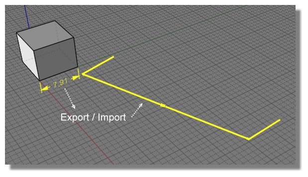
PS Seems there is something wrong somewhere : I don't success to re import in the same Size / View / Position
else dimensions, arrows and lines themselves are good! (except of course surfaces as you said above:)
https://moiscript.weebly.com/uploads/3/9/3/8/3938813/not_same.3dm
From: fcwilt
Hi,
Sorry my bad.
The taskbar shortcut I was using was still invoking the previous beta release.
The current release no longer marks the file as changed on export of STL.
Thanks for fixing that.
Frederick
From: Mik (MIKULAS)
Hi Michael,
concept which I mean is based on Make2D4Views script, which generate 4 views (according viewports views I have set) like most technical drawings, pls see here
https://i.stack.imgur.com/xwJwc.jpg or here
https://en.wikipedia.org/wiki/Engineering_drawing#Line_styles_and_types
This script is perfect, but doesn't offer so many PDF export settings, like in case of solid/surface model, where I can change line styles, hidden lines are automaticly in dashed line style, shaded backround makes drawing more cool if it's necessary.
Therefore I copied and rotated model manually to achieve same arrangement like in case of Make2D4Views script, pls see enclosed.
Re:
>I was thinking something more like in the PDF export dialog there would be a setting for doing 4 views, and also an option for a title block template which could be a separate 3DM file that you had prepared which would get merged into the PDF output. Maybe there's a named rectangle in the title block template file and the exporter fills in that area with that view.
It would be great! Do you mean that final 3DM will contain merged objects in 4 views + block template and then we can start with dimensionsioning or exporter will generate PDF with 4 views + block template, then we import PDF into MOI and start dimensionsioning?
Re:
>Maybe the other piece needed would be a property on dimensions to say whether they display in all views, ortho views only, or 3D view only... ?
Yes, it woud be fine.
Mik
Attachments:
Dim Test.zip
Show messages:
1-6
7-26
27-46
47-66
67-86
87-106
107-126
…
147-158