Show messages:
1-10
…
231-250
251-270
271-290
291-310
311-330
331-350
351-370
…
411-425
From: Frenchy Pilou (PILOU)
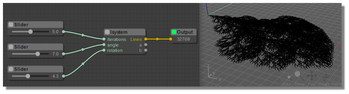
The famous Penrose tilling! The double flying kite! :)
From: Frenchy Pilou (PILOU)
PS There is no .nod file for the Lsystem ? Only a js file ?
Edit : ok Found! :) Just put the JS file inside the folder (for PC) ...\Moi\nodeeditor\nodes\extensions\lsystem.js
Will be in the Node / Objects2 if i am right...
Insert 3 nodes "sliders" a an "OutPut" et voilà!
And so the .nod! ;)
https://moiscript.weebly.com/uploads/3/9/3/8/3938813/lsystem_pil.nod
and the site ;)
https://moiscript.weebly.com/objects2.html#lsystem
Absolutly terrific! Bravo! Another infinite toy!
From: coi (MARCO)
quote:
Lsystem New Node!
eureka, i was asking for something like this 9 years ago
https://moi3d.com/forum/index.php?webtag=MOI&msg=6148.17
tnx
From: wayne hill (WAYNEHILL5202)
Marco / Pilou ,
Very happy you like it.
Wayne
From: Frenchy Pilou (PILOU)
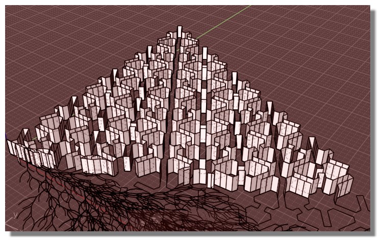
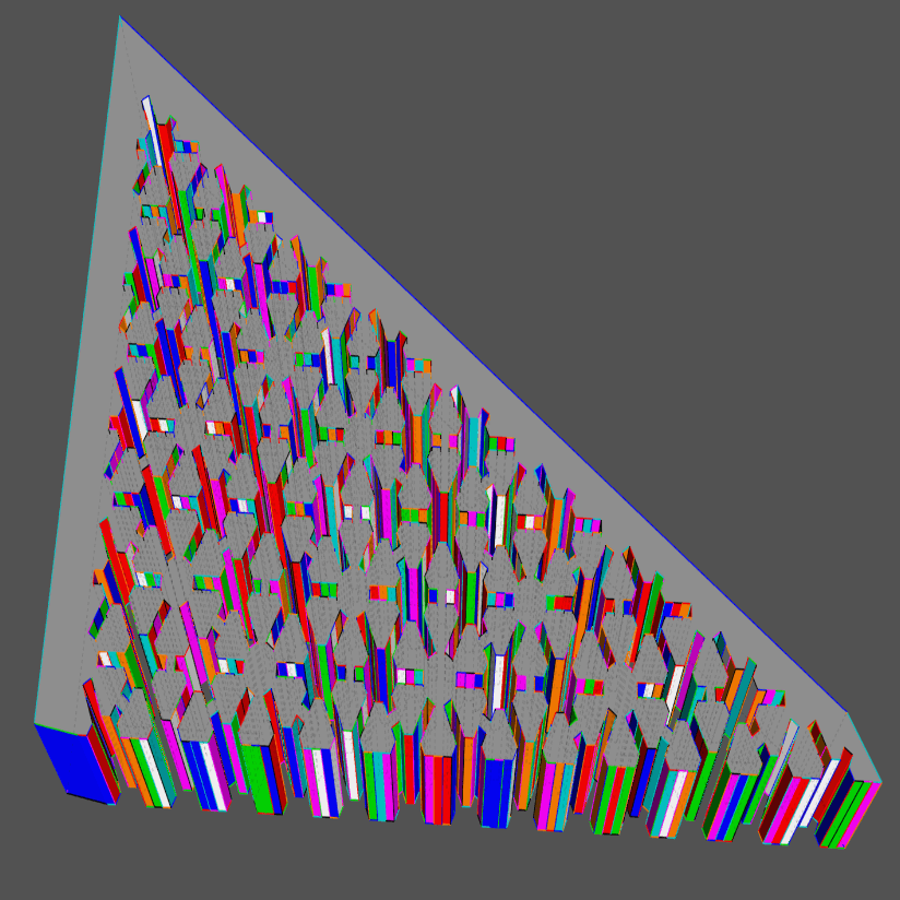
Used for my hundred of the day! ;)
https://imgbox.com/g/tSQCUyur6z
From: wayne hill (WAYNEHILL5202)
A modification to the Node Editor to allow multiple object connections.
It is as simple as commenting out one line on the 'main.js' program.
code:
// >>> if ( this.outputs[slot].type === "objectlist" ) this.disconnectOutput(slot);
code:
LGraphNode.prototype.connect = function (slot, node, target_slot) {
.
.
.
//special case: -1 means node-connection, used for triggers
var output = this.outputs[slot];
if (target_slot === -1) {
	if (output.links == null) output.links = [];
	output.links.push({
		id: node.id,
		slot: -1
	});
} else if (!output.type || //generic output
	!node.inputs[target_slot].type || //generic input
	output.type.toLowerCase() == node.inputs[target_slot].type.toLowerCase()) //same type

	{ // 4-12-2022 wjh
    //  >>>  if ( this.outputs[slot].type === "objectlist" ) this.disconnectOutput(slot);
Image Attachments:
 Multi-Obj_Chg.PNG
From: MO (MO_TE)
Hi
Thank you wayne. With this modification, we can say goodbye to the "clone" node ! :D
Sometimes an indestructible Object appears in the scene.
The problem will solve after saving the scene and restarting moi.
From: wayne hill (WAYNEHILL5202)
Thank you MO!
Here is another one you might like.
Modification to the Node Editor to allow the program name to always appear at the bottom of the display.
Program file 'main.js'
Modify this location:
code:
	//rendering
	if (this.onRender) this.onRender(canvas, ctx);

	//info widget
	if (this.show_info) this.renderInfo(ctx);
Add the five lines to the info widget area:
code:
	//rendering
	if (this.onRender) this.onRender(canvas, ctx);

	//info widget
	if (this.show_info) this.renderInfo(ctx);

	///////////// 4-17-2022 wjh
	ctx.clearRect(0, canvas.height - 20, canvas.width, canvas.height);
	var dpir = this.pixelRatio * this.uiRatio;
	ctx.font = "bold " + 14 * dpir + "px Arial";
	ctx.fillStyle = LiteGraph.NODE_INFO;
	ctx.fillText(this.graph.filename, 5, this.bgcanvas.height - 3 * dpir);
	///////////
Comment out this line. It is a part of a different routine not required.
code:
// >>> ctx.fillText(this.graph.filename, 5, this.bgcanvas.height - 3 * dpir); // 4-17-2022 wjh
From this location:
code:
LGraphCanvas.prototype.renderInfo = function (ctx, x, y) {
	x = x || 0;
	y = y || 0;

	ctx.save();
	ctx.translate(x, y);

	var dpir = this.pixelRatio * this.uiRatio;
	ctx.font = 12 * dpir + "px Arial";
	ctx.fillStyle = LiteGraph.NODE_INFO;
	if (this.graph) {
		ctx.fillText("Total: " + this.graph.elapsed_time.toFixed(0) + " ms", 5, dpir * 15 * 1);
		ctx.fillText("FPS:" + this.fps.toFixed(0), 5, dpir * 15 * 2);
		ctx.fillText("F: " + this.frame, 5, dpir * 15 * 3);
		ctx.fillText(this.graph.blocked ? "Graph blocked" : "", 5, dpir * 15 * 4);
		//  >>> ctx.fillText(this.graph.filename, 5, this.bgcanvas.height - 3 * dpir); // 4-17-2022 wjh
	} else ctx.fillText("No graph selected", 5, 13 * 1);
	ctx.restore();
}
Image Attachments:
NE_filename_Display.PNG
From: MO (MO_TE)
Hi Wayne
I couldn't find the second part of your modification in my "main.js" file:
"LGraphCanvas.prototype.renderInfo = function (ctx, x, y)"
So I just added the first part and it worked.
Thank you
From: wayne hill (WAYNEHILL5202)
Hi Mo,
It is located about line 3891 in the original source code. No real need to comment it out, but good practice to eliminate duplicates.
Here is another modification to try out:
On the Node Editor:
To have the Save function use the current file as the save file instead of typing it in everytime:
On the 'editor.js' file location:
code:
Editor.prototype.onSaveButton = function ()
{
	if (this.graph.blocked) return;
	var saveFilePath = moi.filesystem.getSaveFileName( lang.getTranslation('Save as')+' ..',  lang.getTranslation('MoI Nodeeditor files')+' (*.nod)|*.nod' );
	if ( !saveFilePath ) return false;
	if ( this.graph.status !== LGraph.STATUS_STOPPED ) this.onPlayButton();
	var file = moi.filesystem.openFileStream( saveFilePath, 'w' );
	file.writeLine(LiteGraph.JSONprettify(this.graph.serialize(), {"indent":"	", 'maxLength':150}));
	file.close();
	this.graph.filename = saveFilePath;
	this.graph.setDirtyCanvas(true,true);
}
Change the second line:
code:
var saveFilePath = moi.filesystem.getSaveFileName( lang.getTranslation('Save as')+' ..', lang.getTranslation('MoI Nodeeditor files')+' (*.nod)|*.nod' );
To:
code:
Editor.prototype.onSaveButton = function () {
.
  // wjh 4-19-2022
	var saveFilePath = moi.filesystem.getSaveFileName(lang.getTranslation('Save as') + '..', lang.getTranslation('MoI Nodeeditor files') + ' (*.nod)|*.nod',lang.getTranslation(this.graph.filename));
.
.
}
From: MO (MO_TE)
Thank you for these cool modifications.
You are right.
search didn't work because of extra whitespaces .
LGraphCanvas.prototype.renderInfo = function (ctx, x, y)
LGraphCanvas.prototype.renderInfo = function( ctx, x, y )
Now I find it. :)
I usually prefer to have different versions of same node, But I gave it a try.
I added your modification as you showed, but couldn't see any difference.("save as" window pops up with empty name field)
Anyways, I change your code a bit.
Now if you press the save button and alt key , it saves on existing node file without confirmation.
otherwise works like before.
code:
Editor.prototype.onSaveButton = function (e)
{
	if (this.graph.blocked) return;
	var saveFilePath="";
	// var saveFilePath = moi.filesystem.getSaveFileName( lang.getTranslation('Save as')+' ..',  lang.getTranslation('MoI Nodeeditor files')+' (*.nod)|*.nod' );
	// if (e.altKey) {saveFilePath = moi.filesystem.getSaveFileName(lang.getTranslation('Save as') + '..', lang.getTranslation('MoI Nodeeditor files') + ' (*.nod)|*.nod',lang.getTranslation(this.graph.filename));}

	if (e.altKey) {saveFilePath = lang.getTranslation(this.graph.filename);}
	else {saveFilePath = moi.filesystem.getSaveFileName( lang.getTranslation('Save as')+' ..',  lang.getTranslation('MoI Nodeeditor files')+' (*.nod)|*.nod' );}

	if ( !saveFilePath ) return false;
	if ( this.graph.status !== LGraph.STATUS_STOPPED ) this.onPlayButton();
	var file = moi.filesystem.openFileStream( saveFilePath, 'w' );
	file.writeLine(LiteGraph.JSONprettify(this.graph.serialize(), {"indent":"	", 'maxLength':150}));
	file.close();
	this.graph.filename = saveFilePath;
	this.graph.setDirtyCanvas(true,true);
}
From: James (JFH)
MO,
Your Curves2/ConnectPoints node is very similar to Wayne's Points2/PtsInRange.
Indeed the output is
identical with a "Max Links" setting of 4 or greater & "DistRange" minimum of 0. See below

The facility to generate lines within a range could be added with a dropdown selection as shown above so on "DistRange (min, max)" the "Distance" input would read 2 comma separated numbers.
Perhaps a better, more logical alternative would be to have instead 2 distance inputs: "distMin" & "distMax" with defaults of 0 & 1 respectively. In that way it would operate exactly as it does presently if no connection is made to "distMin" input.
James
https://www.instagram.com/nodeology/
PS I have replied here, in this thread, because the thread
" things about MOI3D that you learn by teaching it." seems a peculiar location for submitting new node contributions. In the interest of accessibility of new nodes to latecomers & infrequent visitor to the forum, we should probably avoid scattering new node submissions across various different threads. This thread & "Nodebundle for playing with nodes" are the 2 established repositories of NE's expanding library of new nodes
Image Attachments:
connectPts.jpg
From: MO (MO_TE)
Hi James
It seems once again I've reinvented the wheel. :)
Although I don't have the "Points2/PtsInRange" node in my NE package.
I changed the "ConnectPoints" node, now it has a range mode.
I get your point about threads.
I'll try to post in related threads.
From: James (JFH)
NODE PROPOSAL: srfNormals

The means of illustrating the surface orientation by displaying normals would offer great utility when working with nodes.
For instance extruding can sometimes give unexpected results due to false assumption of the orientation of faces.
Michael introduced functions for evaluating surface normals by scripts with v4 beta:
face.evaluateNormal( uv ) : Function that evaluates a uv parameter value and returns a normal vector.
I'm not sure whether Michael has builtin a normal vector display or whether it needs to be displayed as per existing vector nodes
See the full list of surface evaluation functions here:
http://moi3d.com/forum/lmessages.php?webtag=MOI&msg=9547.21
Another useful feature would be the inclusion of the facility to unify normals across a polysurface.
Disregard sentence above. Also see link suggested by Michael below:
http://moi3d.com/forum/index.php?webtag=MOI&msg=7777.1620
James
https://www.instagram.com/nodeology/Image Attachments:
srfNormals.jpg
From: Michael Gibson
Hi James, for the display check out here:
http://moi3d.com/forum/index.php?webtag=MOI&msg=7777.1620
That 'arrow3d' factory will make an annotation leader object with the property set on it for rotating the arrowhead plane so it's always facing the viewer. Should be good for a vector direction display.
re:
> Another useful feature would be the inclusion of the facility to unify normals across a polysurface.
This should happen automatically - when surfaces are joined together they should evaluate normals on a consistent side which will be to the exterior if it's a solid.
- Michael
From: James (JFH)
Michael, thank you for your reply.
quote:
This should happen automatically - when surfaces are joined together
Yes I misspoke, I should have said selected surfaces from separated polysurfaces.
Is there a way to ensure that faces remain unified after separating a solid object?
If you look at example below: the half the faces flip after Dodecahedron is separated as demonstrated by the direction of extrusions.

James
https://www.instagram.com/nodeology/
From: Michael Gibson
Hi James,
re:
> Is there a way to ensure that faces remain unified after separating a solid object?
I think that is supposed to be happening automatically already, can you please post your Dodecahedron so I can take a look?
- Michael
From: James (JFH)
Sorry Michael, again I got that wrong. The extrude node was set to "Long"; while the extrusion works as expected in "Union" mode.
However, the issue I have had previously, as it turns out, is not with the maintenance of face normals after separation but rather it seems, a limitation of extrude factory.
If you apply extrude to attached polyhedron (regardless whether separated or not) the extrusions does not conform to face normals, instead they're unidirectional.
I am hoping that the facility to show normals in NodeEditor may be step towards solving this issue.
Sorry again, I should have looked deeper before claiming that the issue was related to surface normals.
Great job with the latest BETA,
James
https://www.instagram.com/nodeology/Attachments:
truncIcosohedron.3dm
From: Michael Gibson
Hi James,
re:
> If you apply extrude to attached polyhedron (regardless whether separated or not) the
> extrusions does not conform to face normals, instead they unidirectional.
It's because the surfaces are not planar. They are degree 1 surfaces with 4 corner points but the 4 points are not all on one plane.
You could do something like evaluate a surface normal at the middle of parameter space and use that as the extrusion direction, but the regular Extrude command will only extrude each piece along a separate individual direction if the piece that's being extruded is planar.
- Michael
From: James (JFH)
Thanks Michael,
quote:
You could do something like evaluate a surface normal at the middle of parameter space and use that as the extrusion direction
Yes this is exactly the method I desire to recreate with nodes, and the principal reason for "NODE PROPOSAL: srfNormals" above.
Thanks for clarifying this.
James
https://www.instagram.com/nodeology/
Show messages:
1-10
…
231-250
251-270
271-290
291-310
311-330
331-350
351-370
…
411-425