The Gate node is one of my meagre contributions to node library from a few years back. http://moi3d.com/forum/lmessages.php?webtag=MOI&msg=7777.1251
At the time I thought these would be a real boon to NE's capabilities; after-all digital computation
is based on logic gates.
Instead it languished; all but ignored (even by me).
When we lost John Conway to covid, I attempted to build a cellular automaton circuit
for his "Game of Life" in NE, however never managed to get it to work.
No, if you reread my post, it was in response to your post about the logic gate node, not L-Systems.
Cellular Automaton replies on conditional logic to test each cell's adjacent neighbours at each iteration to operate,
so it should be possible to build in NE with the use of logic nodes.
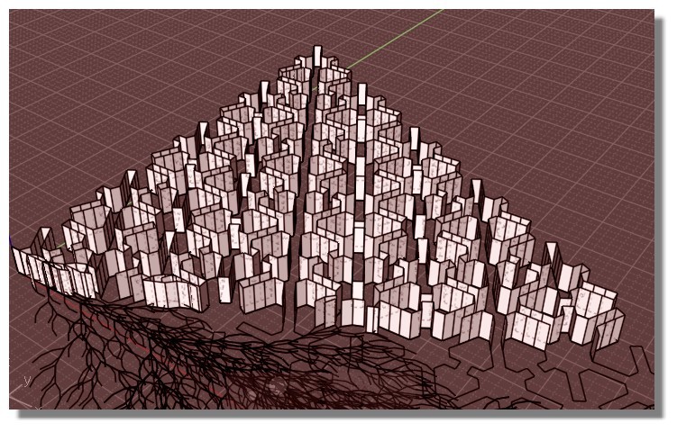
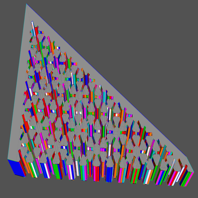
You have an another cellular Automate with a very simple rule!
Turmites : If it's Black turn on the right!
if it's white turn on the left!
Amazing that after some repetition a striah line apaers from the chaos! :)
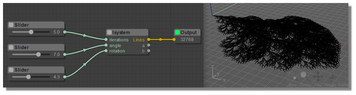
PS There is no .nod file for the Lsystem ? Only a js file ?
Edit : ok Found! :) Just put the JS file inside the folder (for PC) ...\Moi\nodeeditor\nodes\extensions\lsystem.js
Will be in the Node / Objects2 if i am right...
Insert 3 nodes "sliders" a an "OutPut" et voilà!
You are right.
search didn't work because of extra whitespaces .
LGraphCanvas.prototype.renderInfo = function (ctx, x, y)
LGraphCanvas.prototype.renderInfo = function( ctx, x, y )
Now I find it. :)
I usually prefer to have different versions of same node, But I gave it a try.
I added your modification as you showed, but couldn't see any difference.("save as" window pops up with empty name field)
Anyways, I change your code a bit.
Now if you press the save button and alt key , it saves on existing node file without confirmation.
otherwise works like before.
code:
Editor.prototype.onSaveButton = function (e)
{
	if (this.graph.blocked) return;
	var saveFilePath="";
	// var saveFilePath = moi.filesystem.getSaveFileName( lang.getTranslation('Save as')+' ..',  lang.getTranslation('MoI Nodeeditor files')+' (*.nod)|*.nod' );
	// if (e.altKey) {saveFilePath = moi.filesystem.getSaveFileName(lang.getTranslation('Save as') + '..', lang.getTranslation('MoI Nodeeditor files') + ' (*.nod)|*.nod',lang.getTranslation(this.graph.filename));}

	if (e.altKey) {saveFilePath = lang.getTranslation(this.graph.filename);}
	else {saveFilePath = moi.filesystem.getSaveFileName( lang.getTranslation('Save as')+' ..',  lang.getTranslation('MoI Nodeeditor files')+' (*.nod)|*.nod' );}

	if ( !saveFilePath ) return false;
	if ( this.graph.status !== LGraph.STATUS_STOPPED ) this.onPlayButton();
	var file = moi.filesystem.openFileStream( saveFilePath, 'w' );
	file.writeLine(LiteGraph.JSONprettify(this.graph.serialize(), {"indent":"	", 'maxLength':150}));
	file.close();
	this.graph.filename = saveFilePath;
	this.graph.setDirtyCanvas(true,true);
}
Your Curves2/ConnectPoints node is very similar to Wayne's Points2/PtsInRange.
Indeed the output is identical with a "Max Links" setting of 4 or greater & "DistRange" minimum of 0. See below
The facility to generate lines within a range could be added with a dropdown selection as shown above so on "DistRange (min, max)" the "Distance" input would read 2 comma separated numbers.
Perhaps a better, more logical alternative would be to have instead 2 distance inputs: "distMin" & "distMax" with defaults of 0 & 1 respectively. In that way it would operate exactly as it does presently if no connection is made to "distMin" input.
PS I have replied here, in this thread, because the thread " things about MOI3D that you learn by teaching it." seems a peculiar location for submitting new node contributions. In the interest of accessibility of new nodes to latecomers & infrequent visitor to the forum, we should probably avoid scattering new node submissions across various different threads. This thread & "Nodebundle for playing with nodes" are the 2 established repositories of NE's expanding library of new nodes
Hi James
It seems once again I've reinvented the wheel. :)
Although I don't have the "Points2/PtsInRange" node in my NE package.
I changed the "ConnectPoints" node, now it has a range mode.
I get your point about threads.
I'll try to post in related threads.
NODE PROPOSAL: srfNormals
The means of illustrating the surface orientation by displaying normals would offer great utility when working with nodes.
For instance extruding can sometimes give unexpected results due to false assumption of the orientation of faces.
Michael introduced functions for evaluating surface normals by scripts with v4 beta:
face.evaluateNormal( uv ) : Function that evaluates a uv parameter value and returns a normal vector.
I'm not sure whether Michael has builtin a normal vector display or whether it needs to be displayed as per existing vector nodes