Show messages:
1-2
…
223-242
243-262
263-282
283-302
303-322
323-342
343-362
…
503
From: Frenchy Pilou (PILOU)
Thx i will test all that!
About the Text2 that works fine for "number" but that I want is add a Text say a paragraph from any source.
I know that I can input it in the case box of the node itself...but want input from a file ...
Ps about the files from r2d3 i can't have the "concat2" who stay red ! (even loaded the r2d3 .js in extension folder )
else loaded the waves by r2d3 ;)
From: Frenchy Pilou (PILOU)
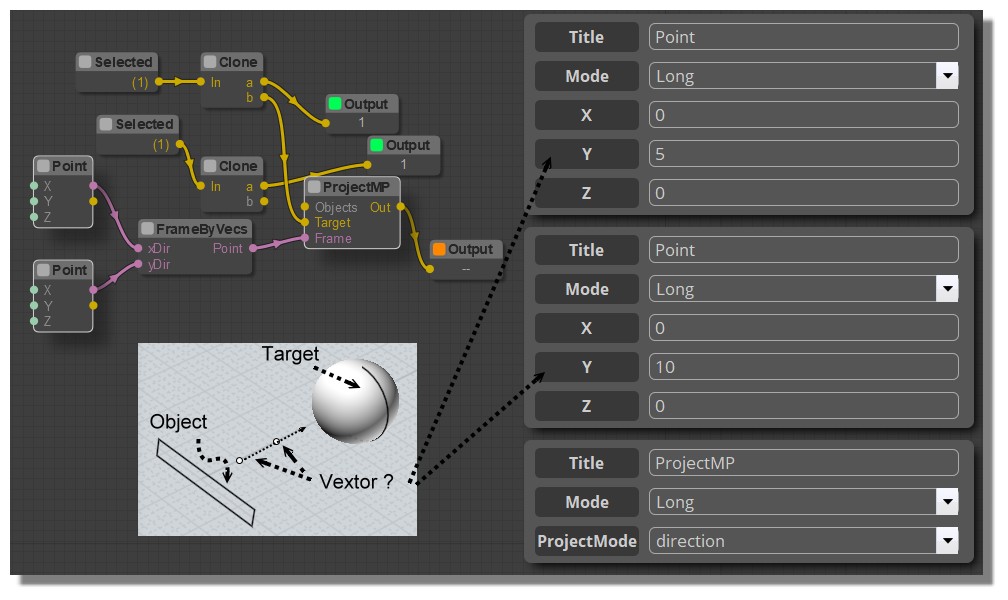
About vectors not better...but it's my lack of use and what is a vector inside Elephant! :)
From: Frenchy Pilou (PILOU)
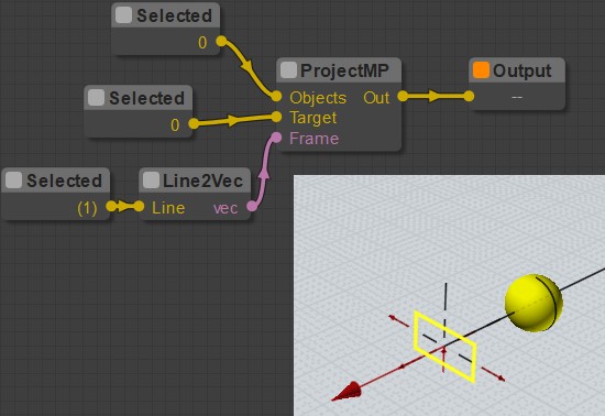
This really draw only the "red ARROW"! Pity because that was cool for draw a vector! :)
I always don't know what the "Frame" is really wanted!
( seems I have a line selected in the good direction)

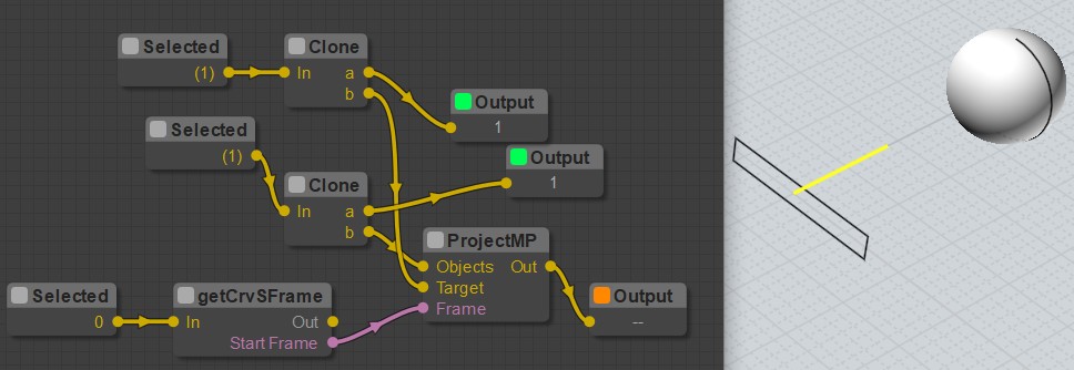
From: Frenchy Pilou (PILOU)
Not better with that! :) Mystery always!
(i run it of course... this image if before the new run ...line is not yet selected)
From: Karsten (KMRQUS)
Hello Pilou,
you can't define a plane/Frame with identical/colinear vectors. X-direction and y-direction have to be different by Default;-)
Have a nice day
Karsten
From: Frenchy Pilou (PILOU)
<< X-direction and y-direction have to be different by Default;-)
I miss the principal trick! :)
But what is indicated the direction toward the sphere ?
Here i want the "Y" ...this frame is an headache for me for the moment! :)
Orient node can be helping ?
From: Karsten (KMRQUS)
Hello Pilou,
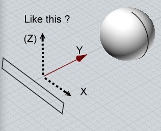
first: Points in the nodeeditor are also Frames. A Frame has an origin that is also a Point. In Your example X-Axis is the x-Axis. Now define a line in the shown z-Axis as your y-Axis Input. The resulting z-Axis is like your y-Axis - only in the wrong direction - but that doesn't matters I think.
That's Basic vector math. The z-vector is the cross product of the x and y vector.
Have a nice day
Karsten
From: Frenchy Pilou (PILOU)
I will meditate that! :!
That's not the technic who affraid me it's the application with nodes! :)
From: Frenchy Pilou (PILOU)
some many tests with this node
no success :(

From: Frenchy Pilou (PILOU)
Size of the red cone is according to the size's line! :)
But always not valide for my Projection by Direction! :(
From: James (JFH)
Pilou,
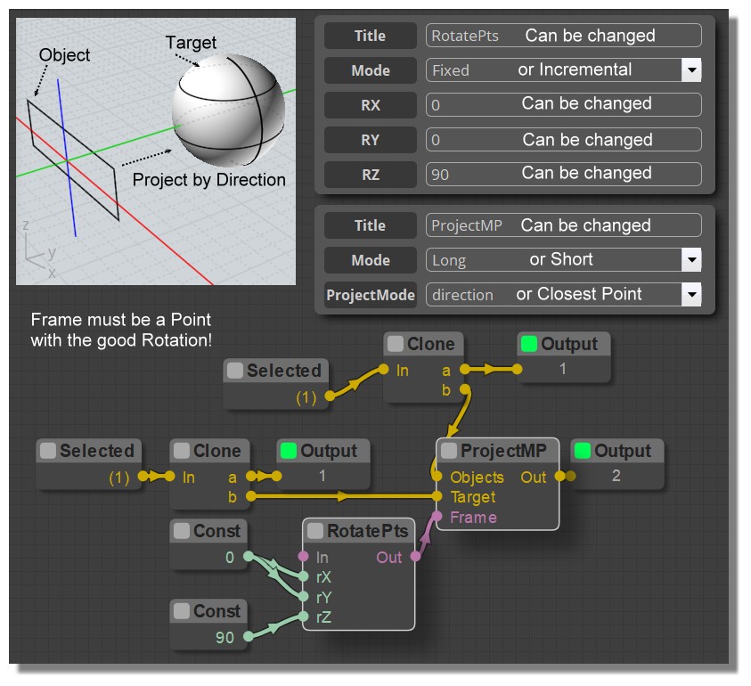
To set the direction in projectMP, use rotatePts like so.
(image a bit blurred in compression: rY value = 90)
Hope this helps
James
https://www.instagram.com/nodeology/

Image Attachments:
 ProfectDirection.jpg
From: Frenchy Pilou (PILOU)
Many thx! So cool the result seems effective!
And seems an only one Point is sufficient as "Frame" if i good understand! :)
Maybe in the futur when i will be more experimented all that will be more automatic!
And maybe find a mnemotechnic trick for have this good point following the position to manage!
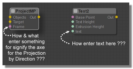
Now rest the ultima thing for the text2 : can we input text (not "number")(from a file maybe cvs(?) in the text input circle button?
From: Frenchy Pilou (PILOU)
Here the Rotation Point must be an another axe! ;)
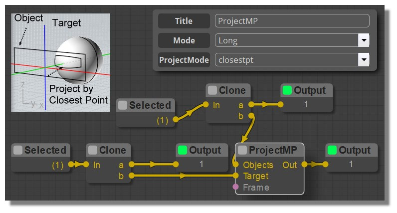
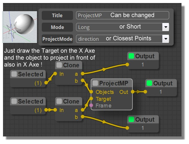
ProjectMp Node
English
http://moiscript.weebly.com/construct2.html#projectmp
From: Karsten (KMRQUS)
Hello Pilou,
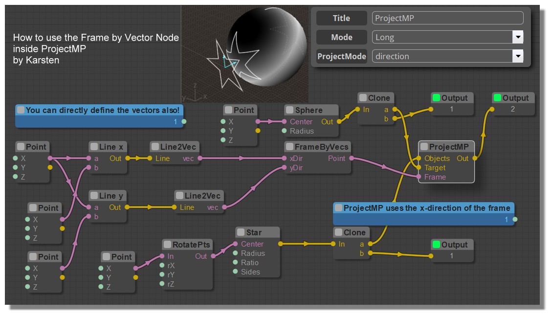
here is an example for using the vectors to create Frames with the vectors. Hopefully the Version I used is up to date.
Have a nice day
Karsten
Attachments:
 ProjectMP.nod
From: Frenchy Pilou (PILOU)
I understand my error : i had read Line2Vec like "Line to Vectors" so completly missed the "FrameByVecs" !!!
So believed that only one line was sufficient...
I must past this on my screen computer! :)
And will added of course in no time here! :)
http://moiscript.weebly.com/construct2.html#projectmp
From: bemfarmer
A Macro CreateFrame could be useful?
- Brian
From: bemfarmer
Hi Karsten,
I am getting an assert failure when doing "apply". After Ignore All, the two vectors cannot be deleted from MoI.
Perhaps unrelated, closing MoI with large nodeeditor canvas, and reopening MoI4beta and nodeeditor results in a large canvas with white top area hidden, and the canvas cannot be moved, unless the canvas is side dragged to be skinnier. (Cannot reproduce this effect...)
I'm trying to understand the frames.
Max incorporated Frames into the PointArray datatype. There is an old post that he made about this accomplishment.
Regarding FrameByVecs:
Adding ConvertPts and Output to the point output of FrameByVecs shows that its output Frame is located as a point at the common beginning point of the two vector inputs,
xdir and ydir.
xdir input establishes the x direction of the output frame. The ydir input does not have to be in the y direction of MoI.
Orthogonality to xdir doesn't seem to matter, as long as ydir has a nonzero value for y or z arrow point of the second input vector.
Karsten's example node uses z = 5 for the ydir vector, but y = 5 would also work, as well as other combinations of z and y.
The axis labels are still not showing up in MoI4 beta.
The addition of 3 outputs to the three vector definition points shows the 3 points to be at the three arrow tips of the 3 Line2Vec nodes.
-Brian
From: Frenchy Pilou (PILOU)
Section Curves2
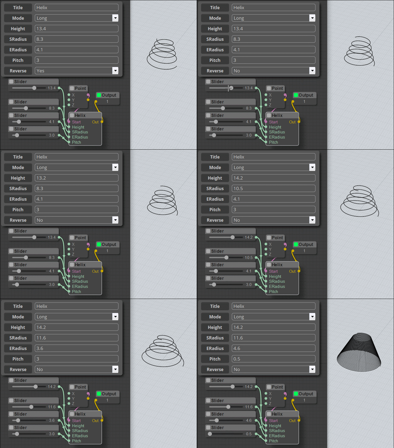
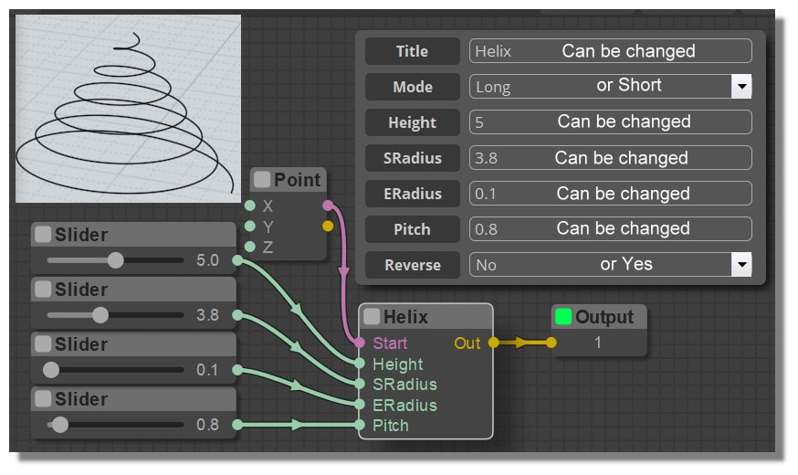
Helix Node
English
http://moiscript.weebly.com/curves2.html#helix
From: Frenchy Pilou (PILOU)
@ karsten : i have resolved my headache! :)
So simple! :)
From: Frenchy Pilou (PILOU)
Section Curves2
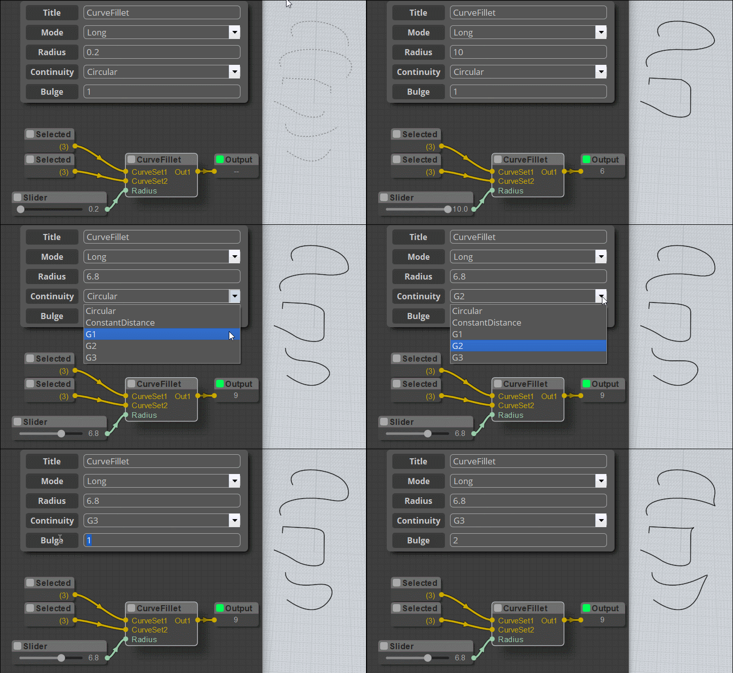
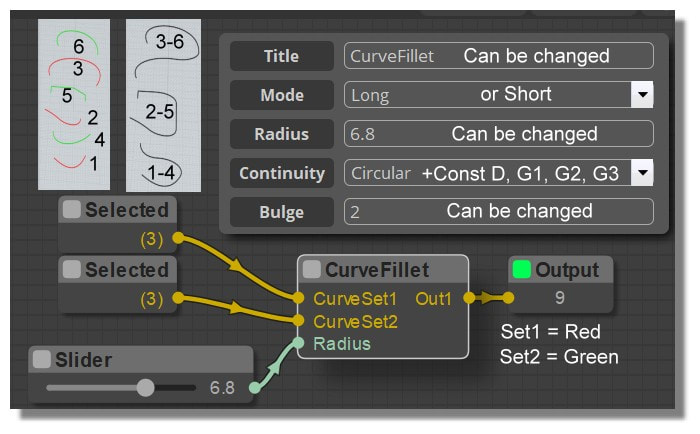
CurveFillet Node
English
http://moiscript.weebly.com/curves2.html#curvefillet
Show messages:
1-2
…
223-242
243-262
263-282
283-302
303-322
323-342
343-362
…
503


![]() ProfectDirection.jpg
ProfectDirection.jpg


![]() ProjectMP.nod
ProjectMP.nod


