Can we move, orient (align) , size the "Blah" text ? (after draw the arrow lines)
Does the "Blah" text has some of these 3 functions as "native" ones when you draw the arrow lines?
and something like "out" (begin, end) "cut" (when inside) arrow lines?
re:
> Another possible work around would be to have 2 perpendicular associated planes with each vector,
> like shown below, however with only one arrow displayed at any one time. The display would be triggered
> on/off (or off/on) based on angle of incidence to screen view.
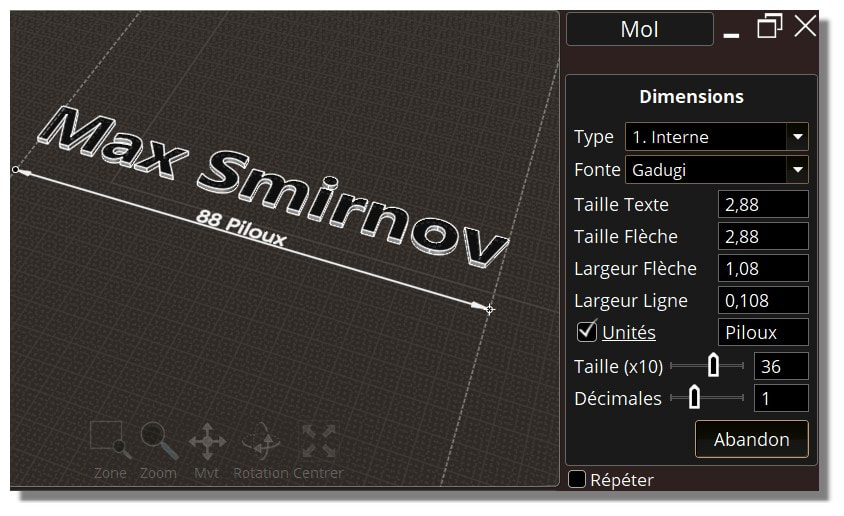
I gave this a try, here's what it looks like:
Doesn't seem too satisfying in removing planar feel to it, if you pause the video at various spots things still seem pretty planar.
On the contrary, I think it is most satisfactory. Vectors after all are just aids for visualising spatial constraint in the construction process; not for final output.
Hi James, ok well it's a quite localized tweak to get that behavior so it should be fine to have a script property on annotation objects that will make it behave like that when set.
Those ones shown in the last video are Leader objects with 2 points.
> Does the "Blah" text has some of these 3 functions as "native" ones when you
> draw the arrow lines?
<< Sorry I don't understand this part.
When you draw your "arrows" does the Text is yet configured for have definited Size, Align (up, down,on), Distance etc... or it's after draw?
Or we can take the "Blah" as an normal object for make any what you want...
re:
> When you draw your "arrows" does the Text is yet configured for has definited Size, Align (up, down,on),
> Distance etc... or it's after draw?
Neither - the text is displayed as a text label on screen more like the object snap tags like "End", "Mid", etc... so it gets its size from the regular UI font size.
Thanks, the extension lines would be fine with that gap.
>For the gap on arrows, would that also apply to the arrows going to the extension lines in a linear dimension like above,
>or only to the arrows on other dimension types?
The arrows can touch the shapes and the extension lines as there is no ambiguity for the reader but the actual ones slightly cross the shapes.
Hi Michel, the arrowhead points do have a few pixels sticking out past the lines, that's due to its wire outline being drawn with mitered corners and anti-aliasing.
You can see the same thing in regular curves in MoI if you just make a line and a pointy triangle:
Max's one doesn't do that because it makes a surface for the arrowhead and surface trim boundaries are not drawn with mitered corners between segments.
If this is troublesome I guess I could make a setting to not miter the arrowhead tip.
>Max's one doesn't do that because it makes a surface for the arrowhead
>and surface trim boundaries are not drawn with mitered corners between segments.
>If this is troublesome I guess I could make a setting to not miter the arrowhead tip.
Thanks for the explanation.
I would prefer the drawing to be as sharp as possible when adding dimensions if it's not too hard or heavy on display performance.
Hi James, here's a different variation on the arrowhead reorienting. This one turns the plane around the arrowhead direction to point as much as possible towards the view direction.
I tried this before but I guess I had something wrong. What do you think, better or worse than the one that switches between 2 planes? :
re:
> I would prefer the drawing to be as sharp as possible when adding dimensions if it's not too hard
> or heavy on display performance.
Well the thing is that mitered corners for the outer line drawing helps make the butt end of the arrow sharp.
It's subtle but here's a comparison - here's #1 with all mitered corners for the outer line:
Here's #2 with the outer boundary as separate lines with no mitered corners at all. The thing I don't like here is if you zoom in to the butt of the horizontal ones you can see it's got a slight rounded appearance instead of very crisp corners:
Here's #3 with only the butt corners mitered and not the tip mitered. It makes a little more blunt tip than it ideally should be but that would also mean the tip won't stick out as much:
Here's #4 with no outer line drawings at all, only a fill:
So number 1 is pretty much the best arrowhead shape that I can make I think. I don't like the butt end of number 2. Number 3 seems like a good compromise it keeps the tip from extending out too much but keeps the butt end sharp. The tip is a little rounded from a perfect arrowhead though. Number 4 seems pretty gross with no antialiasing.
My current thinking is that I'll go with #1 by default but I could have an option to do #3 instead. I'm not sure if #2 or #4 have much value but let me know what you think.
IMO, as an Industrial Designer, non-destructive modeling is a powerful tool as it allows designers to adjust proportions and details *after the fact.* I have always been fascinated by Vitaly Bulgarov's magical sense of proportion and design execution which he creates in MoI. Trying to replicate in polys (the resulting mesh is much more render friendly) has always ended up in a disaster based on lack of proportion correctness-- UNTIL I came across Blender's modifiers.
I coined the term NITROX3D and wrote a post on it at BA:
It's not meant to replace MoI3D, as there still is no solid modeler functions and 3D printing these types of meshes typically requires massive corrections. But creating and editing them is a snap using Blender's modifier stack. Pretty sweet stuff.
It has made me a believer in parametric modeling. And because it's all polys, it happens pretty darn fast versus parametic functions added to the NURBS KERNEL.
@Chipp
it's funny as same technology emerge in the same time on the same prog! :)
Seems SpeedFlow has the same paradigm. "No destructive polygons building" all stay editable.
Am I wrong ? SPeedFlow Companion (2 Addons in the same package) - by a French forum friend - the accent ;) https://pitiwazou.artstation.com/pages/speedflow (big video who show all aspects - see*2 spedd for a better accent! ;)